Water >Stainless steel >Double flanged >lug >Triple Offset >Double Offset >Plastic >Seat >Diagram >High temperature >Grooved >Rubber Lined >Piping >Crane >Concentric >Resilient Seated >Stem >Large >Pneumatic >pvc >Threaded >Exhaust >Gate Valve >Audco >Keystone >Sanitart >Drawing >Bray >Cast Iron >Gearbox
BUTTERFLY VALVE MANUFACTURERS SYDNEY NSW AUSTRALIA-BUTTERFLY VALVE SUPPLIERS SYDNEY AUSTRALIA-BUTTERFLY VALVES DISTRIBUTORS SYDNEY AUSTRALIA
A butterfly valve is a specialized control valve used to control liquid or gas flow through pipes. The rotating disc in the valve is controlled by an exterior wheel, allowing it to be completely shut off when necessary. Butterfly valves contrast with valve types like steel globe valves, steel gate valves, check valves, and solenoid valves.
For over 20 years, pacificfc has manufactured a world-leading range of cast and forged steel gate, globe, check, ball, triple-offset butterfly, knife gate, highly engineered severe service valves and steam traps offering superior performance across all major industrial applications. We concentrate on designing, manufacturing and marketing advanced technology steel valves in a range of types and sizes.
Australia pacificfc.com.au Valve Company has made a commitment to being the best, most responsive valve supplier in the industry, a commitment to quality and service that started over 100 years ago. From concept, through engineering, manufacturing, installation and service, every valve reflects the Company's customer commitment. Our ISO9001-certified facilities manufacture over 4,000 manual and actuated valves.
When it comes to butterfly valves, you have come to the right place! We have been producing excellent quality valves since we first opened our doors. All of our products are put through extensive rigorous testing before leaving our state of the art facility to further ensure 100% quality assurance! Allow us to show you the difference when you work with true professionals! Contact us via telephone or email or check out our website today!
If you are looking for the best AWWA butterfly valves in the country, you've come to the right place! We have some of the most skilled manufacturers and technicians in the world today working on our products. We take pride in our work, and we always manufacture our valves in-house. You can trust us to provide outstanding quality each and every day. Contact us for additional information!
Less friction, low torque, less wear, longer life. Unlike other valves that seal with friction, Posi-flate�s unique butterfly valve uses an inflatable seat to seal with air pressure. Thus it requires less torque and a smaller actuator, resulting in lower cost. Plus, the seat automatically compensates for wear, providing longer life. Some users have reported over 6 million cycles and the valves are still going strong.
Archon Industries is a manufacturer and distributor of processing equipment. We provide butterfly valves-stainless steel with heat-insulated handle plus clamp end, manual and butt-weld for the brewing and wine industries. We are your reliability solution when it comes to varieties of valve equipment. At Archon Industries, Inc., customer service is at our top priority. Call us today for a quote!
One of the first people to use the butterfly valve was Scottish engineer and chemist James Watt. Watt used them as an important hardware element in his steam engine designs in the late 1700s. People did not really begin using butterfly valves in earnest, though, until the 1870s, when engineers used them as a part of a device with which they controlled air and steam flow to fans and turbines.
As time went on, manufacturers were able to make butterfly valves that were smaller, lighter, more powerful, and more heat resistant. One of the most important changes for butterfly valves came after World War II, when engineers started manufacturing them with seal accessories. These seals were made from synthetic rubbers. With them, butterfly valves became suitable for a much wider range of applications.
While the general design and function of a butterfly valve has remained largely unchanged with time, some of the fabrication processes have changed due to advances in technology and knowledge. For example, manufacturers now understand more about how particular metals will react to fluctuations in temperature and high or low pressure. This knowledge helps to prevent costly system malfunctions and valve failures. Improved CNC machining equipment also makes it possible to cut the valve assemblies with such extreme precision that leaks are not possible and the pipe remains fully blocked off when the valve is shut.
Based on application specifications, manufacturers can create butterfly valves that come in a diverse series of standard sizes and custom sizes, and a wide range of hardware choices. For example, in some cases, manufacturers might design the shaft as two pins rather than one solid rod. To learn more about your custom options, talk to a butterfly valve supplier.
The disc works like a gate in the gate valve, the plug in the plug valve, the ball in the ball valve, etc. When it rotates 90� to be parallel to the fluid flow, the disc is in open position. In this position, the disc will permit all fluids to pass. When it rotates again, the disc enters closed position and blocks fluid flow. Based on disc orientation and design, manufacturers can manipulate operating torque, sealing, and/or flow.
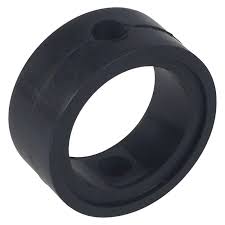
The seat is connected to the body via pressing, bonding, or a locking mechanism. Manufacturers usually make the seat from a polymer or elastomer. The goal of the seat is to provide the valve with shut-off. That is why the value of turning force that a butterfly valve requires to close is called �seating torque,� and the turning force that a butterfly valve requires to rotate its closure element is called �unseating torque.�
There are several types and series of butterfly valves, each with a unique purpose. These include high performance butterfly valves, pneumatic butterfly valves, butterfly valves with multiple shut-off points, triple offset butterfly valves, flanged butterfly valves, wafer style butterfly valves, lug butterfly valves, traditional butterfly valves, electric butterfly valves, AWWA certified butterfly valves, plastic butterfly valves, stainless steel butterfly valves, and aluminum butterfly valves.
Stainless steel butterfly valves are used in applications where resistance to corrosion and oxidation is important for consistent performance. Stainless steel is not only corrosion resistant and oxidation resistant, but also easy to clean and sanitize. Unlike many butterfly valve types, stainless steel butterfly valves can be used in food and medical applications.
Butterfly valves offer many advantages to their users. First, they feature a compact design. Because of this compact design, they require less space to work than many other valves. Second, butterfly valves are fairly low maintenance. Next, they provide high quality flow blocking. Likewise, they do not leak, yet they are easy to open when you need to. Another advantage of butterfly valves is the fact that they are inexpensive.
If you are interested in purchasing butterfly valves for your application, we recommend you connect with a high-quality butterfly valve manufacturer. To help you find the right one, we have put together a list of some of the best butterfly valve suppliers in the business. You�ll find the profiles and contact info of these companies by scrolling towards the middle of this page.
Before you start looking at our list of butterfly valve manufacturers, though, we suggest you take some time to write down your specifications. This will help you focus your search and focus your later conversations with potential suppliers. Make sure your specifications list includes information like your delivery deadline, your budget, your standard requirements, and your customer support preferences. Once you have written all of those down, take a look at our list of suppliers. Based on your specifications, pick three or four in which you are most interested. Then, reach out to each of those manufacturers to discuss your application. After you have spoken with each of them, compare and contrast your conversations and the services that each company offers. Finally, decide which manufacturer is right for you. Good luck!
A butterfly valve is a valve used for flow regulation in large pipe diameters in which the disc takes the form of disk. Operation is similar to that of a ball valve. A plate or disc is positioned in the center of the pipe. The disc has a rod passing through it that is connected to an actuator on the outside of the valve. Rotating the actuator turns the disc either parallel or perpendicular to the flow. Unlike a ball valve, the disc is always present within the flow, therefore a pressure drop is always induced in the flow, regardless of valve position.
Actuated Butterfly Control Valves, control the flow of gas or liquid by means of a disk, which turns on a diametrical axis inside a pipe or by two semicircular plates hinged on a common spindle, which permits flow in only one direction. These valves offer a rotary stem movement of 90 degrees or less, in a compact design. Unlike ball valves, they do not have any pockets in which fluids may become trapped when the valve is closed. They are quick opening valves that consist of a metal circular disc or vane with its pivot axes at right angles to the direction of flow in the pipe, which when rotated on a shaft, seals against seats in the valve body. They are normally used as throttling valves to control flow.
New digital high resolution controller for use in the Flomatic FCEL Series Electric Actuators. The DHC-100 is a high resolution controller/positioner: - for use in the FCEL series AC electric actuators - with operating times from 2 to 120 seconds - that can be configured for various command types (4-20mA, 1-5V, 0-5V, 0-10V, or a digital command) and a fail position on loss of signal With its modular design a variety of options are easily plugged in providing other features. A wide range of data is accessible through a digital communications module providing additional control and information.
Pressure Max: 200 PSI (14bar) Working Temp: Max+180�F (82C) MODEL 45 - Electric actuated, Azure� butterfly valve, 110 vac power, manual handwheel override for open/close service. - Cast ductile iron flanged body. ASTM A536 Cast ductile iron disc with stainless type 316 edge. Seat, standard NBR (EPDM optional)bonded and vulcanized. Complies with AWWA standard C504. Direct mounting of actuator. Size(s): 3 to 24 in. (80 to 240 mm)
Whether it�s critical, lethal, toxic or aggressive, you�ll find Pacificfc valves doing the job around the world. That�s because extended service life, safe operation and environmental protection are at the core of every valve we manufacture. Global customers can easily find the configurations they require, engineered to meet requisite performance and safety standards, whether it�s a standard or custom-engineered solution. It�s a portfolio of brands for quarter-turn, rotary, linear, control and specialty configurations that covers today�s toughest demands for valve performance. But we�re looking ahead to the new challenges that will test the current state of valve manufacture. This mindset pushes us to continually pursue advancements in materials and severe-duty enhancements and the next levels of precision control, optimized flow and fail-safe shut-off.
Industrial sites around the world trust Pacificfc to provide unmatched control for the most difficult fluid management applications. The exacting design and manufacturing of our quarter-turn, rotary, linear, control and specialty valves result in reliable performance, extended service life, and safe operation in a wide range of applications and environments. Read our updated valve and actuation catalog � which includes more than 150 flagship valve, actuation and instrumentation products � and see how Pacificfc products can help you achieve world-class valve performance.
Ideal for precision throttling and on-off applications, especially in lighter-weight piping systems, the Pacificfc family of butterfly valves is often specified for its versatility. Outstanding throttling accuracy for process control is achieved through low-friction, erosion resistant sealing surfaces with very low operating torques. A broad range of applications can be met via metal- and soft-seated designs as well as lined versions for corrosive and hygienic applications.
Pacificfc is a leading provider of flow control products and services for the global infrastructure markets. Pacificfc recognizes and supports the privacy interests of all persons, and we respect these interests when we collect and process Personal Data. This Privacy Notice explains our information practices and the choices you can make about the way your Personal Data is collected and used through our websites.
Pacificfc and its affiliates (collectively �Pacificfc�, �we�, �us�, or �our�) maintain and operate this and other websites including applications (collectively, the �Pacificfc Websites� or �Websites�). Because some applications, such as those hosted by a third party on our behalf, may require additional information, or use information in a different way, they may have their own privacy policies and terms and conditions. These applications may also offer you additional choices for managing your Personal Data.
A cookie is a small text file that is placed on your computer�s hard drive by your web browser when you visit a website. Cookies enable websites to access information about the pages you visit and your actions and preferences (such as login, language, font size, and other display preferences) over a period of time. Pacificfc uses cookies to ensure the functioning of the Websites, as well as to provide better service when users return to our Websites. For example, using cookies with the Websites allows you to come back to the Websites or browse without having to resubmit your preferences and other information. In certain instances, Cookies may be considered Personal Data.
Maintaining the security of your information is very important to Pacificfc. We use reasonable technologies to keep your Personal Data secure, and we implement reasonable security measures, that are designed to protect against the accidental or unlawful destruction loss, misuse, alteration, unauthorized disclosure of, or access to your Personal Data.
Pacificfc is a multinational corporation, headquartered in the United States with offices, affiliates, employees, representatives, partners, and service providers located around the world. As a result, Pacificfc may transfer your information, including your Personal Data to, or process your information in, the United States and/or countries other than the country in which your information was collected or provided.
We may share your information, including your Personal Data within the Pacificfc group of affiliates to facilitate the business relationship and provide the best customer experience. Furthermore, we may share your information with third parties that assist us with fulfillment of our business objectives, job applicant screening or with the performance and content of our Websites. In the event we sell, assign or transfer all or part of the Pacificfc business, we may transfer your personal data to the buyer.
Pacificfc Websites may provide links or other directions to the websites of our distributors, sales representatives or other third parties. If you follow a link to a third-party website, please note that we are not responsible for the protection and privacy of any Personal Data you provide while visiting such websites. We encourage you to read third-party websites� privacy policies and statements.
Pacificfc does not track users� behavior on our Websites or across websites for the purpose of serving targeted ads and therefore our Websites do not respond to browser Do Not Track (DNT) signals. Third parties that have content embedded on Pacificfc�s Websites may set cookies on a user�s browser and/or obtain information about the fact that a web browser visited a specific Pacificfc Website from a certain IP address. Third parties cannot collect any other Personal Data from Pacificfc�s websites unless you provide it to them.
Pacificfc may update this Privacy Notice from time to time as our business, services, or policies change, or as required by law. We encourage you to visit our Websites periodically to stay informed about Pacificfc's privacy practices. If we update this Privacy Notice, we will post the updated version of the Privacy Notice on our Websites. Your use of the website following any update to the Notice means that you accept the updated Privacy Notice.
Pacificfc takes reasonable steps to ensure your Personal Data is accurate and up-to-date for the purposes for which it was collected. We encourage you to contact us to update or correct your information if it changes or if you believe that any information we collected about you is inaccurate. Please note that to honor your request, we may require additional information for authentication or other verification purposes.
Pacificfc is committed to fulfilling our responsibilities in relation to collection, retention, use and other processing of Personal Data that is within the scope of GDPR. Such Personal Datawill be processed only for lawful and appropriate purposes. Pacificfc has implemented reasonable measures designed to secure Personal Data and to prevent unauthorized or accidental access, erasure, or other misuse of personal data. Pacificfc will facilitate the exercise of Data Subject rights in an effective and transparent manner.
Pacificfc may transfer your Personal Data across borders to Pacificfc and our representatives, affiliates, third party partners and service providers in the United States and other countries where we do business. In the event of a cross-border transfer of your Personal Data, if the country to which we transfer your Personal Data is not a recipient of an adequacy decision from the European Commission, and if the transfer is not made under a derogation that does not require additional suitable protections, then we provide appropriate or suitable safeguards for such cross-border transfers as required by law, via the EU standard contractual clauses.
Pacificfc retains your Personal Data only for as long as is reasonably necessary to accomplish the purposes for which it was collected, and as permitted by applicable law. In many cases, this will require retention through the period of the business relationship, or as needed for business administration, tax and/or legal purposes. We may retain backups and archives that may include your Personal Data as long as reasonably necessary to comply with applicable law.
In certain circumstances, Pacificfc will need to use your Personal Data even though you may have asked us to delete or restrict or if you objected to our use of it. If this is necessary, we will do so in a lawful, fair and transparent manner. Furthermore, if you revoke consent, prior uses and disclosures will not be affected, and we may otherwise continue to process Personal Data as permitted or required by law.
Operation is similar to that of a ball valve, which allows for quick shut off. Butterfly valves are generally favored because they cost less than other valve designs, and are lighter weight so they need less support. The disc is positioned in the center of the pipe. A rod passes through the disc to an actuator on the outside of the valve. Rotating the actuator turns the disc either parallel or perpendicular to the flow. Unlike a ball valve, the disc is always present within the flow, so it induces a pressure drop, even when open.
A butterfly valve is from a family of valves called quarter-turn valves. In operation, the valve is fully open or closed when the disc is rotated a quarter turn. The "butterfly" is a metal disc mounted on a rod. When the valve is closed, the disc is turned so that it completely blocks off the passageway. When the valve is fully open, the disc is rotated a quarter turn so that it allows an almost unrestricted passage of the fluid. The valve may also be opened incrementally to throttle flow.
There are different kinds of butterfly valves, each adapted for different pressures and different usage. The zero-offset butterfly valve, which uses the flexibility of rubber, has the lowest pressure rating. The high-performance double offset butterfly valve, used in slightly higher-pressure systems, is offset from the centre line of the disc seat and body seal (offset one), and the centre line of the bore (offset two). This creates a cam action during operation to lift the seat out of the seal resulting in less friction than is created in the zero offset design and decreases its tendency to wear. The valve best suited for high-pressure systems is the triple offset butterfly valve. In this valve the disc seat contact axis is offset, which acts to virtually eliminate sliding contact between disc and seat. In the case of triple offset valves the seat is made of metal so that it can be machined such as to achieve a bubble tight shut-off when in contact with the disc.
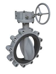
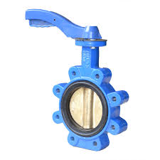
Lug-style valves have threaded inserts at both sides of the valve body. This allows them to be installed into a system using two sets of bolts and no nuts. The valve is installed between two flanges using a separate set of bolts for each flange. This setup permits either side of the piping system to be disconnected without disturbing the other side.
A lug-style butterfly valve used in dead end service generally has a reduced pressure rating. For example, a lug-style butterfly valve mounted between two flanges has a 1,000 kPa (150 psi) pressure rating. The same valve mounted with one flange, in dead end service, has a 520 kPa (75 psi) rating. Lugged valves are extremely resistant to chemicals and solvents and can handle temperatures up to 200 �C, which makes it a versatile solution.
Rotary valves constitute a derivation of the general butterfly valves and are used mainly in powder processing industries. Instead of being flat, the butterfly is equipped with pockets. When closed, it acts exactly like a butterfly valve and is tight. But when it is in the rotation, the pockets allow dropping a defined amount of solids,[1] which makes the valve suitable for dosing bulk product by gravity. Such valves are usually of small size (less than 300 mm), pneumatically activated and rotate 180 degrees back and forth.
In the pharmaceutical, chemical, and food industries, a butterfly valve is used to interrupt product flow (solid, liquid, gas) within the process.[2] The valves used in these industries are usually manufactured according to cGMP guidelines (current good manufacturing practise). Butterfly valves generally replaced ball valves in many industries, particularly petroleum, due to lower cost and ease of installation, but pipelines containing butterfly valves cannot be 'pigged' for cleaning.
The butterfly valve has been in use since the late 18th century. James Watt used a butterfly valve in his steam engine prototypes. With advances in material manufacturing and technology, butterfly valves could be made smaller and withstand more-extreme temperatures. After World War II, synthetic rubbers were used in the sealer members, allowing the butterfly valve to be used in many more industries.[3] In 1969 James E. Hemphill patented an improvement to the butterfly valve, reducing the hydrodynamic torque needed to change the output of the valve.[4]
208 butterfly valve diagram products are offered for sale by suppliers on Pacificfc, of which valves accounts for 3%. A wide variety of butterfly valve diagram options are available to you, There are 9 suppliers who sells butterfly valve diagram on Pacificfc.
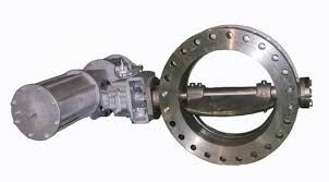
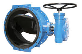
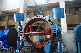
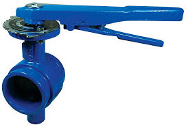
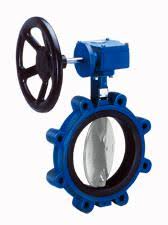
Large Butterfly valves are usually equipped with gearbox type actuator, where the handwheel is connected to the stem via a gearbox. This will reduce the force but at the same time reduce the speed of the operation. This type of valve should be installed in the open position. If the valve is closed during installation, the rubber seat will wedge against the valve disc and make it difficult to open.
Butterfly valves are low-pressure valves of efficient design which are used to control and regulate flow. They are characterized by fast operation and low pressure drop. They require only a quarter-turn from closed to full open position. Butterfly valves are available with metal-to-metal seats, soft seats and with fully lined body and disk. The soft seats permit bubble-tight shut off and the full lining enhances erosion and corrosion resistance.
Most symbols suited for a wiring diagram look like abstract versions from the real objects they represent. For example, a switch will be a enter the fishing line which has a line at an angle towards the wire, similar to a light switch it is possible to flip on and off. A resistor is going to be represented having a number of squiggles symbolizing the restriction of current flow. An antenna is often a straight line with three small lines branching off at its end, much like a genuine antenna.
A wiring diagram typically offers information concerning the loved one position and also setup of tools and terminals on the devices, in order to help in building or servicing the gadget. This differs a schematic representation, where the arrangement of the parts� interconnections on the diagram usually does not represent the parts� physical places in the finished gadget. A photographic representation would show more information of the physical look, whereas a wiring diagram utilizes an extra symbolic symbols to stress affiliations over physical look.
The electric signs not just reveal where something is to be mounted, however also exactly what type of device is being installed. A surface ceiling light is shown by one symbol, a recessed ceiling light has a various symbol, and a surface area fluorescent light has an additional icon. On large tasks signs might be numbered to show, for example, the panel board as well as circuit to which the gadget connects, as well as likewise to identify which of a number of kinds of component are to be mounted at that area.
Butterfly valves can be used for a broad range of applications within water supply, wastewater treatment, fire protection and gas supply, in the chemical and oil industries, in fuel handling systems, power generation etc. Some of the advantages for this type of valve are the simple construction not taking up too much space, and the light weight and lower cost compared to other valve designs.
Butterfly valves typically pivot on axes perpendicular to the direction of flow inside the flow chamber and are situated on a spindle that allows for flow in a single direction. They are frequently used as throttling devices, controlling the levels of flow in entirely closed, entirely open or partially open positions. Butterfly valve suppliers stock numerous closure types and body configurations, depending on the type of flow control needed and the design.
Butterfly valves are commonly composed of metals like cast iron, aluminum and stainless steel, but can also be made from various plastics. Butterfly valves are designed and sold in many diameters, resulting in different flow rates. Smaller butterfly valve assemblies may be used where space is limited. Butterfly valves are used in many food transporting and chemical plants where controllable product flow is required. Other specific applications include HVAC, petroleum recovery and industries that use high pressure water.
Butterfly valves are fairly simple in design. When prompted, the disc rotates and stands upright in the pipe, resting on a seal or gasket and forming a tight seat. The design offers many benefits. First of all, they generally have a long life cycle. Butterfly valves are easy to maintain, lightweight and compact and able to handle a wide range of temperatures.
These valves are also very reliable because of their tight shutoff, reducing the amount of leakage. These butterfly valves are categorized as rotary valves, which are generally recognized by the quarter turn that is used to move from the open to closed position and back again. This results in a lower surface friction, which means that these valves can be smaller than others and still operate efficiently.
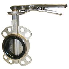
Compared with ball valves, butterfly valves do not have pockets to trap fluids when the valve is in the closed position. A certain kind, flanged butterfly valves, can be mounted between flanges. Another, the lug butterfly valve, uses metal inserts that are attached to the valve's bolt holes. Using an independent set of bolts for each flange, this butterfly valve's assembly is fixed between two flanges. Finally, wafer butterfly valves are the cheapest and most popular type of butterfly valves because of their simplicity and ease of use.
A butterfly valve is used to shut off or modulate the flow of a fluid (isolation and regulation). PACIFICFC 609 Centric butterfly valves (soft seated) are preferred to gate and ball valves for low-pressure and non-critical applications as they are cheaper, lighter and easier to install. Eccentric butterfly valves (double offset and triple offset valves) with metal seats have surged in popularity and compete with globe and ball valves for some applications.
You can send mail or call us directly. Business scopes spreads to middle China,West China,East China,South China and 76 countries &areas all over the world. We are familiar with all types of enterprises development strategy. Through reliable products and perfect services, the brand of Bundor has won extensive praise from customers.
Bundor has 117 products patents and passes CE, CU-TR, PACIFICFC, WRAS, ISO9007, ISO18001, ISO14001, AAA credit grade certificate. Strictly in accordance with ISO, PACIFICFC, JIS, DIN and other standards for valve production, the factory has a perfect enterprise standardization system, has more than 80 sets of high-precision mechanical equipment and quality testing equipment. Can provide more than 10000 kinds of valve models, with a perfect computer system, with independent product research and development capabilities.
Bundor valve is located in jinan area, tianjin city, is a collection of scientific research, design, production, sales and after-sales service as one of the professional valve manufacturers, its main export port is tianjin port. Tianjin port is an important comprehensive port and foreign trade port in north China. After the order is confirmed, production can be arranged in 24 hours to ensure the delivery time. Bundor valve always adhere to science and technology and quality peers, dare to innovate, the pursuit of excellence.
Founded in 1990s, Bundor is an experienced manufacturing and trading combo specialized in the research & development, production and sales of Butterfly valve, gate valve, check valve, globe valve and other valves. 25 years adhering to the principle of manufacturing process of competent valve fittings, the control of valve manufacturing throughout all the production processes, so that "Bundor" has become the world's leading supplier of water system valve.Our team
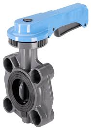
Resilient-seated butterfly valves are the most basic design and are also commonly called concentric or resilient-seated butterfly valves. In this type of valve, the stem is centered in the middle of the valve disc, which is centered in the pipe bore. This valve typically has a rubber (or resilient) seat and relies on the disc having a high level of contact with the seat to effect a seal. The disc will contact the seat the earliest (�85�) during the 90� rotation.
PACIFICFC valves are durable resilient-seated valves that feature a one-piece body for reduced weight and increased strength. Their unique stem hole design in the disc ensures a dry stem journal, and the hard-backed seat enables ease of installation, reliable operation, and field replacement without special tools. PACIFICFC valves are well proved in industrial and commercial applications.
Single-offset butterfly valves have a stem that is located behind the disc. There are few, if any, valves of this type on the market today because of the development of the double-offset, or high-performance, valve. The single offset of the stem causes the disc to contact the seat with 3� to 4� left to travel; this design was enacted because less seat contact is thought to enable longer valve life.
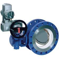
Double-offset (high-performance) butterfly valves have a disc with two offsets and can be rated up to 1,480 psi [10 MPa]. Similar to a single-offset design, the double-offset butterfly valve has a stem which is located behind the disc. With the high-performance butterfly valve, the second offset�s stem is moved once more off the center of the disc to one side. This offset geometry enables the 90� disc rotation to rub over the seat for only 1� to 3� of the 90� rotation.
Both resilient and high-performance butterfly valves can be operated by handles, gears, or actuators. These devices move the valve disc to the optimal position for complete shutoff or fully open the valve. Resilient and high-performance butterfly valves are used mainly in the water, chemical, and petrochemical industries and can also be used in fuel handling systems, power, and many other applications.
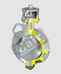
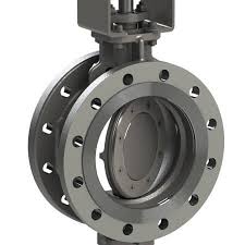
Triple-offset valves (TOVs) are applied in difficult services in which reliable performance under harsh conditions is required. Exactly like a double-offset valve, the stem is located behind the disc and offset to one side (double offset). The third offset is the geometry of the seating surface. This seating surface creates a cone shape of the disc and seat that wedges into the seat with minimal contact between the sealing surfaces until the valve is fully closed. By reducing the amount of contact that the seat has with the disc, sealing becomes more efficient, and the life of the valve is extended.
Unlike single- and double-offset butterfly valves, TOVs are typically metal seated. The Cameron WKM TOV has a metal-seat design, which enables achieving zero leakage (per PACIFICFC 598) in either direction for extreme services. The true triple-offset geometry of the WKM TOV enables bubble-tight (per PACIFICFC 598) sealing to create a fully bidirectional zero-leakage shutoff valve.
PACIFICFC, a professional manufacturer of butterfly valve established in the year 2003, After 15 years of development, we have extensive experience in the production and processing of butterfly valve. Our butterfly valve stocks have always 2,800 units , which make us to offer the fastest delivery shipment.
All our butterfly valve molds are designed and manufactured by ourselves. We have a professional technical team and R&D team. 15% of our annual business income is used for new product R&D and design. We can provide you with OEM, ODM services. The main products are: wafer butterfly valve, lug butterfly valve, flanged butterfly valve, lined PTFE butterfly valve, pneumatic butterfly valve, electric butterfly valve for medium flow cutoff, flow adjustment.
pacifcfc firmly adheres to the quality policy and goal of �improving continuously and seeking zero defect". We have established the internal quality assurance system at a level higher than international, domestic standards and customer requirements for the implementation of comprehensive, whole-course quality management. pacificfc is provided with the first-class inspection center where various tests and inspections from product prototype test till product final inspection are independently completed.
Holding the principle of �innovation is the source of quality�, pacificfc is always giving priority to technical research and development, and constantly improving product performance to better meet actual demands of customers. We are leading the industry with our top-notch scientific research personnel. The cutting-edge software strength ensures our products are leading the way at the R&D stage. The development of every new technology...
Having present through out Australia, you will get all your choicest brands under one roof from trusted Butterfly Valve distributers. You can procure Butterfly Valve from reliable Butterfly Valve dealers in India. When you buy Butterfly Valve online in Australia, don�t miss out on the attractive deals that pop up now and then with every item. You don�t have to worry about the genuineness of our products as we hoard from best Butterfly Valve distributors who know the best. If you purchase Butterfly Valve at Industry buying, you will experience the ease of shopping. And also get the best Butterfly Valve prices.
1,765 price butterfly valve products are offered for sale by suppliers on Pacificfc, of which valves accounts for 81%, firefighting equipment accounts for 1%. A wide variety of price butterfly valve options are available to you, such as high pressure, low pressure. You can also choose from manual price butterfly valve, as well as from stainless steel, plastic, and alloy price butterfly valve There are 1,765 suppliers who sells price butterfly valve on Pacificfc.
List Prices - the prices shown on the website, where a discount is also shown, are generally LIST prices for the end user and not re sellers. The discounts are generally quantity based to encourage bulk purchasing. If there is not a discount shown, this is a net price which we have priced to sell. Although we show prices on the website, if you are not happy with the price or can buy cheaper elsewhere, challenge us to better your current buying price....
Here on the image above, you can see commonly used symbols for valves. These symbols are generic in nature � for example, the first symbol of a valve. Now when you look at the symbol on drawing, it just gives you an indication that some kind of valve is used, but it will not provide you with information about the type of valve whether it is a gate, globe or plug type valve. There are dedicated symbols for a gate, globe, plug, ball valves which I will explain you in minutes.
Here on the image above, the first symbol is of angle valve. In most cases, a globe valve is used as an angle valve. Next symbol is of relief valve that used to protect the piping system or equipment from overpressure. Now the breather valve is used on the cone roof tank. This valve serves the function of the relief valve and vacuum valve. In the event of over-pressure, this valve release the pressure and in case vacuum are created in the tank, this valve allows air to enter the tank. Just like breathing air in and out.
Image above, you can see the gate valve. Now see the P&ID symbol for gate valve. It is a modification of a generic valve symbol by inserting a vertical line between two triangles. Three symbols shown below are the gate valve symbols used in isometric drawings. The first is for butt-welding ends, second is for flanged end valve and the third one is for socket end connection.
Direction and location of installing the butterfly valve should be ease to operate, although installation may cause difficulties but operator will benefit in the long run. Manual operator of the valve should be chest height (1.2 meter above ground) for easier operation when opening and closing the valve. For valve installed on the ground, manual operator should face upwards and not lean to one side. Space should be provided for operator to operate the valve. For valve installed against the wall, installer should avoid situation which operator have to operate facing upwards, especially when media passing through the valve are acidic or toxic.
The seat in a resilient-seated butterfly valve usually extends around to both faces of the valve. As a result, no gaskets are required as these seats serve the function of a gasket. The seat material which extends past the face is compressed during installation and flows toward the centre of the valve seat. Any change in this configuration due to improper installation directly affects the pressure rating and seating/unseating torques.
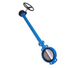
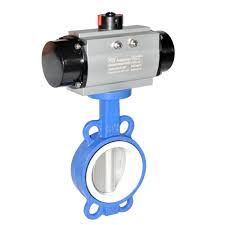
The structure of the wafer butterfly valve is short, take up the space is little,when installing, first use the special flange for the wafer butterfly valve to fix it, and then place the fixed wafer flange in the middle of the flanges at the two ends of the pipe, and use the bolt to pass through the special flange and pipe flange of the clip-on butterfly valve. By fixing it, the fluid medium in the pipeline can be controlled (if there is no flange on the pipeline, the special flange of the butterfly valve needs to be welded to the pipeline). The wafer butterfly valve's small footprint makes it particularly suitable for applications where space is limited or where the distance between pipes is relatively small.
Remove all packing materials surrounding the valve and carefully lift it from the container. Caution, for large or heavy valves, the appropriate material for handling equipment must be used to prevent injury and/or possible damage to the valve. PACIFICFC recommends keeping the shipping container and all packing material for reuse in storage or reshipment.
If valves are not going to be installed immediately, they should be stored indoors in a clean, dry, corrosion free environment without direct exposure to sunlight. The discs should remain in the nearly closed position to protect the sealing edge and to prevent distortion of the resilient seat. No other maintenance during storage or use is required.
PACIFICFC butterfly valves are bi-directional and may be installed with flow in either direction, vertically, or horizontally. If a choice of stem position exists, the valve should be installed with the stem in the horizontal position; this will minimize seat wear by distributing the stem and disc weight evenly. Also, if the media is abrasive, the horizontal stem position creates a self-flushing effect that will extend the service life-expectancy of the valve.
If disc is not aligned parallel to the ends, for lever style � slightly loosen top plate (by loosening 2 bolts), turn lever clockwise until disc is centered & parallel to ends, and re-tighten top plate. For gear operated valve, adjust hex nuts on side of gearbox. Fully open and close disc several times to assure proper operation. If re-alignment is necessary, repeat.
Open the valve slowly to the full open position to assure free unobstructed disc movement and that there is no contact with the piping or mating flanges. Note that disc interference may result when valves are installed in pipelines having smaller than normal inside diameters, such as heavy wall pipe, plastic-lined pipe, as-cast flanges or reducing flanges. Interference can also occur when connecting directly to a swing check or silent check. Suitable corrective measures must be taken to remove these obstructions, such as taper boring the pipe, or installing a spacer or spool piece.
Valve Body � Grease fitting is located on the neck of the valve. As received, the body does not contain grease. For severe applications, slowly apply grease through fitting until excess can be seen between the shaft and Teflon seat. If Teflon bushing begins to �blow� out, relieve excess pressure by removing grease fitting. Once pressure is relieved, push Teflon bushing back into valve, and re-install grease fitting.
PACIFICFC International, Inc. maintains a stock of flanges in a variety of alloys, rubber expansion joints, valves and various other pipe fittings for the HVAC, Irrigation, Exhaust, Process, Water Works, Mining, Power, Tunneling, and Communication Tower industries. These items are stocked in one of our conveniently located warehouses for quick distribution throughout the United States.
At Pacificfc we specialise in Building and Construction Data Acquisition and Signal Conditioning Electrical and Electronics Flow Control and Fluid Transfer Fluid Power Imaging and Video Equipment Industrial and Engineering Software Industrial Computers and Embedded Systems Lab Equipment and Scientific Instruments Manufacturing and Process Equipment Material Handling and Packaging Equipment Materials and Chemicals Mechanical Components Motion and Controls Networking and Communication Equipment Optical Components and Optics Semiconductors Sensors, Transducers and Detectors Specialized Industrial Products Test and Measurement Equipment All Product Catalogs
Acetal Acetal polymers are semi-crystalline. They offer excellent inherent lubricity, fatigue resistance, and chemical resistance. Acetal suffers from outgassing problems at elevated temperatures, and is brittle at low temperatures. Glass filled, and added lubrication grades are available, flame-retardant grades are not. Brand names include Celcon� (Hoechst Celanese), Delrin� (DuPont), Thermocomp� (LNP), Ultraform� (BASF), and Acetron� (DSM).
Brass / Bronze Brass comes with good strength, excellent high temperature ductility and reasonable cold ductility, good conductivity, excellent corrosion resistance, good bearing properties and low magnetic permeability. Sintered bronze is a porous material, which can be impregnated with oil, graphite or PTFE. Not suitable for heavily loaded applications but useful where lubrication is inconvenient.
Cast Iron The term "cast iron" refers not to a single material, but to a family of materials whose major constituent is iron, with important trace amounts of carbon and silicon. Cast irons are natural composite materials whose properties are determined by their microstructures - the stable and metastable phases formed during solidification or subsequent heat treatment. The major microstructural constituents of cast irons are: the chemical and morphological forms taken by carbon, and the continuous metal matrix in which the carbon and/or carbide are dispersed.
Polyethylene (PE) Commodity thermoplastic that is soft, flexible and tough - even at low temperatures - with outstanding electrical properties but poor temperature resistance. It also has very good chemical resistance but is prone to environmental stress cracking; it has poor UV resistance (unless modified) and poor barrier properties, except to water.
PVDF Polyvinylidene fluoride (PVDF) is a melt processable fluoropolymer. It is similar in properties to other fluoropolymer, but has better strength and lower creep than the other members of this family. PVDF has good wear resistance, and excellent chemical resistance. But does not perform well at elevated temperatures. Brand names include: Kynar� (Elf AtoChem).
All Sure Flow Butterfly Valves meet PACIFICFC-609, MSS SP-67, and ISO 5752 face-to-face dimensions. Butterfly Valve sizes from 2″ to 12″ are rated at 250 psi WOG service and valve sizes from 14″ and larger are rated at 200 psi WOG service. All Butterfly Valves are full rated on dead-end service. All Butterfly Valve bodies are ductile iron 65-45-12. They are bi-directionally tested in both directions and are bubble tight with zero leakage. Lug style bodies are full rated and suitable for ASME Class 125 and ASME Class 150 flanges. Wafer style bodies are suitable for ASME Class 125, ASME Class 150, JIS, DIN or B.S. flanges. Secondary seals are self-adjusting. All elastomers and all internal bearings are non-corrosive and non-metallic. EPDM seats are suitable for 250�F sustained high temperature and capable of 2000 ppm on chlorinated applications.
Butterfly valves are quarter-turn rotary motion valves used as throttling valves to control flow through a system. They can be used with many different media. Butterfly valves offer several advantages including quarter-turn, openness for less plugging, and good control capabilities. They may be used in a wide variety of chemical services, are available with small dimensions allowing for use in areas where space is limited, and allow a high coefficient of flow. Disadvantages include difficulty cleaning internal parts; therefore they should be avoided in situations that call for sterile, medical or food processing applications. Additionally, some styles may have difficulty dispensing slurries.
The closure element of a butterfly valve consists of a metal circular disc or vane that pivots on an axis at right angles to the direction of flow in the pipe. When rotated on a shaft, the disc seals against seats in the valve body. The thin disc is always in the passageway but it offers little resistance to flow. These valves offer a rotary stem movement of 90 degrees or less, in a compact design. Unlike ball valves, butterfly valves do not have any pockets in which fluids may become trapped when the valve is closed. The valve operation time is short because the valving element is rotated a quarter turn to open or close the passageway.
Control valves are an important part of a fluid handling system. Selecting a butterfly valve for this function requires more calculations and allow for system requirements. The user must be able to identify the maximum flow requirement, which is equivalent to the design flow, and maximum pressure drop allowed, which is provided by the consulting engineer and is usually three to five pounds maximum. This pressure drop should never exceed one half of the inlet pressure.
Double eccentric designed valves are also known as high performance valves. The sealing plane of the disc is offset from the axis of rotation, this leads to uninterrupted circular sealing surface on the disc that makes it possible for a circular sealing element to be placed in the valve. The axis of rotation of the disc is laterally displaced from the center so it will move away from the seat in order to prevent jamming as the valve opens and closes. Double eccentric valves eliminate wear points around the disc at the top and bottom of the seat as well as extending the life of the valve's leak-free performance. Seats are available in metal or plastic. Metal seats are long lasting but do not provide as good a seal as soft plastic seats such as polytetrafluoroethylene (PTFE) and filled PTFE.
Triple eccentric designed valves have a metal sheet which ensures a strong conical sealing principle. The centerline of the cone is rotated away from the valve centerline resulting in an ellipsoidal profile and providing the third offset. There are three offets to the design; the center of rotation is offset from the tightness surface to allow for a total contact around the complete seal, the center of rotation of the disc is offset from the pipe centerline to allow a seal opening valve, and the seal cone tilting cancels jamming and friction. This allows for complete tightness without seal deformation and the seat-seal interface is completely eliminated ensuring long-sealing life. The design is durable even under extreme temperature fluctuations and pressures drops.
Gas: Valves for gas systems seal tightly up to a minimum specified leakage rate at rated operating temperatures and pressures. When there is a small volume, the use of the equal percentage characteristic* is recommended. For large volumes the linear characteristic* is preferred if more than 25% of the system pressure drop is available to the valve.
Solids: When using a valve for semi-abrasive or abrasive material applications (including slurry applications) there are several things that should be considered. A disc closing on dry bulk material will create premature wear on the rubber seat and the obstructed orifice created by the disc may cause bridging of material on the inlet side of the valve. Other considerations include the potential of the disc jamming on dry materials or the material becoming trapped between the disc and seat causing conveying line inefficiencies.
The lug body has protruding legs that provide bolt holes matching those in the pipe flange. This style has metal inserts installed in the valve's bolt holes. The valve is installed between two flanges using a separate set of bolts for each flange. The advantage of the lug body style is it allows for dead-end service or removal of downstream piping.
The wafer body style is installed between two flanges using bolts or nuts and studs. It does not have protruding legs. The shape is light-weight and has a lower initial and installation cost. However, some wafer body styles will not form a proper seal so care should be taken to avoid placing it between slip-on or screwed flange types. Wafer style valves are easier to replace and install.
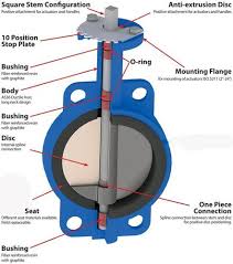
Valve seat- Most butterfly valves use an elastomeric seat and the disc seals against it. The seat utilizes an interference fit between the disc edge and the seat to provide shutoff. The flow is stopped when the valve disc seals against a seat on the inside diameter of the valve body. It may be bonded to the body or pressed or locked in. Other seal arrangements use a clamp-ring and backing-ring on a serrated edge rubber ring to block extrusion of the O-ring. In high-performance designs, the seal maybe provided by an interference-fit seat design of a line-energizes seat design. The seal is created by the pressure in the pipeline increasing the interference between the seat and disc edge. The seats of inexpensive valves may be molded into the body and cannot be repaired or replaced but in most precision valves the seats are repairable and replaceable.
Valve disc and stem assemblies- Butterfly valves have separate stem and disc pieces that are fastened together by one of two methods. In the first method, the stem is secured with bolts or pins that go through the disc. The second method allows the disc to "float" and find its center in the seat by shpacificfcng the upper stem bore to fit a squared or hex-shaped stem. The second method of assembly can be used for corrosive applications because external stem fasteners are eliminated and covered discs can be used. The disc is held in position by the stem which must stand beyond the bottom of the disc to the bottom of the valve body. The seal is accomplished with an O-ring or standard stuffing box. The fluid in the system will come into contact with the seal so it is important to pick a steal durable enough for the media used in the system. Since the stem in most butterfly valves is protected from the media, the material can be selected with respect to cost and mechanical properties. However, in high performance types the stem is in contact with the media so the stem material must be compatible. The stem must also provide the required strength to seat and unseat the disc from the seat.
Manual/ hand operated actuators use a hand-wheel or crank to open or close the valve. They are not automatic but offer the user the ability to position the valve as needed. Manual actuators are used in remote systems that may not have access to power, however they are not practical for applications that involve large valves. The hand-wheel can be fixed to a stem or hammer which allows for the valve to be pounded open or closed if necessary. Gear-heads can be added for additional mechanical advantage and open/close speed.
Solenoid operated valves use hydraulic fluid for automatic control of valve opening or closing. Manual valves can also be used, with a solenoid valve, for controlling the hydraulic fluid; thus providing semi-automatic operation. A solenoid is a designed electromagnet. When an electric current is applied, a magnetic field is generated around the wire. An iron "T" or plunger is put in the center of the coil to concentrate the magnetism. Since iron is a strong magnetic conductor and air is not, the "T" is drawn by the magnetic field into a position where the magnetism can travel 100% through the metal conductor. The moveable "T" acts as the actuator of the valve. Solenoid valves can be arranged such that power to the solenoid either opens or closes the valve. One application of solenoid valves is to supply the air to systems like pneumatic valve actuators. These valves are not practical for large systems because their size and power requirements would be excessive.
Electric motor actuators permit manual, semi-automatic, and automatic operation of the valve. Electric actuators are the most common actuator type for butterfly valves because the valve can be operated remotely, and the actuator is reliable and maintenance-free. The high speed motor is usually reversible and used for open and close functions. The actuator is connected through a gear train to reduce the motor speed and thereby increase the torque. The actuator is operated either by the position of the valve or by the torque of the motor. A limit switch can be included to automatically stop the motor at fully open and fully closed.
Hydraulic actuators provide for semi-automatic or automatic positioning of the valve. They are used when a large force is required to open the valve, such as a main steam valve. With no fluid pressure, the spring force holds the valve in the closed position. Fluid enters the chamber, changing the pressure. When the force of the hydraulic fluid is greater than the spring force, the piston moves upward and valve opens. To close the valve, hydraulic fluid (such as water or oil) is fed to either side of the piston while the other side is drained or bled. Hydraulic actuators are available in a wide range of sizes and are economical to use in a valve system as well as with a single valve.
Fast acting actuators are best used when a system must be quickly isolated or opened. Fast action is provided by hydraulic, pneumatic, and solenoid actuators. The speed of actuation is set by installing the correct orifice in the lines and the valve is closed by spring pressure, which is opposed by hydraulic or pneumatic pressure to keep the valve open. Electrical motors can also provide fast actuation when the speed is set through the motor speed and gear ratio. Fast acting valves quickly increase the flow rate in increments as it travels through the valve when the valve position is near closed. Except for pressure-relief applications, the fast acting characteristic is rarely used for control applications.
Due to the wide variety and variations in valves, the actuator must be sized to the specific valve in the system. If the actuator is undersized, it will be unable to overcome the forces against it. This will cause slow and erratic stroking. If the actuator is not stiff enough to hold the closed position, the closure element will slam into the seat, causing a pressure surge. If the actuator is oversized, it will cost more, weigh more, and be more sluggish in terms of speed and response. Larger actuators may also provide a higher thrust that will damage internal valve parts. Actuators tend to be oversized because of safety factors but smaller sizes function just as well when built-in safety factors are considered.
Valves are made of a wide variety of materials including metallic and nonmetallic options. When selecting a material, the operating environment (i.e. ambient heat), lifespan (i.e. maintenance), and media (i.e. gas or corrosive liquid) should be considered. The most common material is carbon steel because it responds very well to high heat, is easily available and inexpensive. However, it is not suited for corrosive materials. Stainless steel is strong and exhibits resistance to both corrosion and high temperatures, but costs more than carbon steel. Special alloys are used for severe applications such as high pressure or extremely corrosive materials.
The valve flow coefficient is the number of U.S. gallons per minute of 60�F water that will flow through a valve at a specified opening with a pressure drop of 1 psi across the valve. The coefficient is used to determine the size that will best allow the valve to pass the desired flow rate, while providing stable control of the process fluid. For a control valve, the flow rate is related to the opening of the valve. There are two relationships available to determine flow rate.
Pressure drop is the change in pressure that occurs between the inlet and outlet of the valve. It's an important specification to understand when selecting the size of the butterfly valve needed. If the pressure drop across the fully opened valve is not a large enough percentage of the total system drop, there will be little change in the fluid flow until the valve closes. In this case, a fast acting valve would be appropriate.
Sizing is very important when selecting a butterfly valve as a throttle device. Since there is no pressure drop across an open/close system, the inlet and outlet ports are generally the same size. In this case, the size of the valve is determined by the volume of media going through the system and the flow coefficient. There are several variables to consider when determining sizing for a valve. First is what type of media the valve will be controlling. The specific gravity and viscosity of the media will affect flow rate. Second is the maximum inlet pressure and temperature, along with the outlet pressure (pressure drop) at maximum load. Third is the maximum capacity and last is the maximum pressure drop the valve must close against.
Since butterfly valves are high capacity, a very small pressure drop is required to control the flow, which allows for reduction from the line size when sizing a valve. This pipe reduction affects the flow characteristics and will reduce the effective flow rate of the valve. This is known as the piping geometry factor. The pipe geometry factor can be adjusted for using below.
plastic butterfly valve, aluminum butterfly valves, water butterfly valves, cora butterfly valves, keystone butterfly, vacuum butterfly valve, ceramic butterfly valve, hydraulic butterfly valve, audco valve butterfly, cavitation butterfly valve, wafer type butterfly valves, 3 way butterfly valves, 4 inch butterfly valves, pacificfc 609 butterfly valves, awwa butterfly valves, pacificfc butterfly valve, sanitary butterfly valve, triple offset butterfly valves, automatic butterfly valves, awwa c504 butterfly valves, bronze butterfly valves, butterfly valve control valve, butterfly valve mtv, butterfly valve stainless, cast iron butterfly valves, pacificfc butterfly, ductile iron butterfly valves, electric butterfly valves, exhaust butterfly valves, flanged butterfly valves
As you search our website and browse our publications, you may click on product information provided by our affiliates, or within a publication on editorial or sponsored content. Periodically, these affiliates, editorial sponsors, and sponsored content providers will reach out to you via email to determine if you have additional interest in their product or service.
Bray Valves including Resilient Seat, Double Offset, Fire Safe Butterfly Valves & Bray/VAAS Knife Gate Valves. Bray valves are industry certified and trusted by thousands of businesses worldwide for their reliability and proven design features. Take a look at our Bray butterfly valves including the Series 30, 31, 40 & 41 & Bray/VAAS Knife Gate Valves. Valves Online are the Official Online Partner for Bray.
As recommended by REVIT users, due to the variety of configuration options for 3-way Butterfly valve assemblies, Bray recommends the following; �Place (1) 2-way Bray Automated butterfly valve in the master orientation required. �A standard ANSI 125/150 3-way tee which can be found in the above file �Place (1) 2-way Bray Manual Butterfly valve in the slave orientation as required
Bray Resilient Seated Butterfly Valves are known worldwide for their durable design, unique industry leading features, and outstanding value to the end user. Bray offers more series and options of valves than any other resilient seated butterfly valve manufacturer in the world. The Series 30/31 raised the bar and now sets the industry standard. Bray also pioneered the development of the Nylon 11 disc (N11) disc. This unique disc material can be used where stainless steel is specified for a fraction of the price. Bray Lug Valves come standard with Ductile Iron bodies. Standard seat materials include EPDM, BUNA, (FKM-Viton), and teflon. Bray standard disc materials include DI-N11, Ductile Iron, Aluminum Bronze, Stainless Steel. Resilient Seated valves are available to pressure ratings of 250 PSI.
Pacificfc can be a tremendous resource for Resilient Seated Bray Valves. We can provide bray valve dimensions, part number breakdowns on bray valves, and who sells bray valves. Our Bray Resilent Seated Inventory includes Series 30 and Series 31 in common trims up to 20". Bray Series 20/21 thru 12" in both resilient seats, teflon seated, and teflon lined. Bray 31H valves in N11 disc and SS disc up to 20" As well as Bray spare parts including discs, replacement seats, packing, etc.
Pacificfc High Performance Butterfly Valves offer the end user second to none performance at a great value. Bray pacificfc valves are utilized in industries such as power generation, pulp & paper, steel manufacturing, aluminum manufacturing, oil and gas pipeline, petroleum refineries, food and beverage, and the HVAC industry. Bray pacificfc valves feature a high-strength one piece blow out proof stem, adjustable packing, precision fit taper pins that into reamed holes, an internal travel stop and a engerized encapsulated seat. Standard body materials include both carbon steel and stainless steel. Options for the Bray pacificfc include PTFE and UHMWPE seats, Fire-Safe Trim, Hastelloy C bodies, Alloy 20 trim, Monel discs for Chlorine, Cryogenic trims, and High Temperature trims.
FloSource stocks one of the most comprehensive inventories of pacificfc in North America. Our inventory includes Carbon Steel Lug and Wafer ANSI 150# valves up to and including 24" in both Carbon Steel and Stainless Steel bodies. ANSI 300# valves in carbon steel and stainless steel through 12" in both lug and wafer. We also carry ANSI 600# pacificfc valves thru 8" in Carbon Steel Lug and Wafer.
The technology of the butterfly valve has evolved gradually throughout time and its usage has become more popular nowadays. This valve comes from the family of quarter turn valves in different sizes, intended for different uses and handling different levels of pressure, the greater the size of the valve, the higher the pressure that it can handle (you can know more this at butterfly valve selection guide article). In coherence with all mechanical devices, this piece of equipment has different parts or components that contribute in its functionality and usefulness in everyday life.
The first part of the valve to be tackled is the disk. Since this valve is a flow control device, it incorporates the use of a rotating disk which serves as the passageway of the material that the valve controls. An early use of these devices was mainly in controlling the flow of water. This makes sense since the valve is designed and can definitely be used to regulate and isolate the gush of water. Nowadays, these valves are also used to regulate the flow of chemicals in certain factories and also used to control the entry and exit of air in a carburetor of a car.
Typically, this valve has four main components, namely: the body, seat, operator or valve handle, and disk. High performance valves like this usually have a body that would usually fit in between two pipes. Most common body designs are the lug and the wafer. The lug type has these protruding lugs that provide bolt holes, while the wafer type does not have these protrusions and instead, is placed in between the pipes flanges and this in turn surrounds the bolt holes. Both types have their equal share of advantages and disadvantages. The wafer type costs less, but this design does not transfer the weight of the piping system directly through the body. And the lug type is more expensive, but allows removal of downstream piping.
Next up on the list is the seat of the valve. This seat utilizes the interference fit between the edge of the disk and the seat to provide shutoff for the valve. The seat may either be bonded to the body or locked in. The materials of these are usually made out of polymers or in some cases, out of metal. Having these metal seats would allow resistance up to a higher temperature.
The disk, as illustrated earlier, acts as a passageway for the valve. Many variations and attempted experiments on improving the disk have showed capabilities such as improving the rotation of the disk and quality of the disk itself and sealing and increasing the level of torque. Last but not the least is the operator or the valve handle. Obviously, this is used to operate the valve in increasing or decreasing the flow. This is an important component since without this; the butterfly valve would not be much a valve, would it?
Many different types of valves are used in flow control. They are used for a variety of reasons, such as phase (liquid or gases), pressure, piping restrictions and solids content. Other valves are chosen for their capability to open and close in a quarter turn. Of all the valve types, the butterfly valve is used as a control device for many reasons including some or all of the above.
There are many advantages offered by butterfly valves compared to other types of valves including an inherently simple, economic design that consists of fewer parts, which makes butterfly valves easy to repair and maintain. The wafer-shaped body and relatively light weight offer a savings in the initial cost of the valve and installation costs -- in person-hours, equipment and piping support.
Body. Butterfly valves generally have bodies that fit between two pipe flanges. The most common body designs are lug and wafer. The lug body has protruding lugs that provide bolt holes matching those in the pipe flange. A wafer body does not have protruding lugs. The wafer valve is sandwiched between the pipe flanges, and the flange bolts surround the body.
In high-performance butterfly valves, the shutoff may be provided by an interference-fit seat design or a line-energized seat design, where the pressure in the pipeline is used to increase the interference between the seat and disk edge. The most common seat material is polytetrafluoroethylene (PTFE) or reinforced PTFE (RTFE) because of the wider range of compatibility and temperature range.
Lined butterfly valves rely on elastomers (rubber) and/or polymers (PTFE) to completely isolate the valve body and stem journal area from the corrosive and/or erosive effects of the line media. When the body and stem journal area are isolated from the line media, the valve is considered a "non-wetted" design. By isolating the valve body and stem with rubber or PTFE, it is not necessary for the valve body to be made of expensive corrosion-resistant materials such as stainless steel, Alloy 20 and C-276.
For example, if a valve travel change from 20% open to 30% open produced a 70% change in flowrate, then a valve travel change from 30% open to 40% open would produce another 70% change in flowrate. If the flowrate at 20% open was 100 gpm, then flowrate at 30% open would be 170 gpm and the flowrate at 40% open would be 70% greater than at 30% travel or 289 gpm. The same would be true for each additional incremental travel position.
Quick opening. A quick-opening valve means exactly that. Flowrate through the valve increases very rpacificfcdly for incremental changes in valve travel when valve position is near closed. As valve position becomes more open, flowrate changes diminish with incremental changes in valve travel approaching zero change as the valve position nears full open.
The selection of the appropriate control valve characteristic is dependent on the needs of the system. Because there are several factors to be considered, a complete system analysis is required to determine precisely which is the optimum characteristic. Often, it is not practical to perform a system analysis; therefore, certain rules of thumb are offered:
Bray's Series 3A/3AH resilient seated butterfly valve is a Double Flanged design which can be used for dead-end service. A major design advantage of Bray valve product lines is international compatibility. The same valve is compatible with most world flange standards � ASME Class 125/150, BS 10 Tables D and E, BS 4504 NP 10/16, DIN ND 10/16, AS 2129 and JIS10. In addition, the valves are designed to comply with ISO 5752-Table 2 (EN558 Table 13) face-to-face and ISO 5211 actuator mounting flanges. Therefore, one valve design can be used in many different world markets.
In piping following types of valves are used depending on the requirements. The cost of Valve in the piping system is up to 20 to 30% of the overall piping cost. And the cost of a given type and size of the valve can vary 100%. It means that if you choose ball valve over butterfly valve for the same function. It can cost you more. So, the selection of valves is essential to the economics, as well as operation, of the process plants.
Gate valve is the most common type of valve in any process plant. It is a linear motion valve used to start or stop fluid flow. In service, these valves are either in fully open or fully closed position. Gate valves are used in almost all fluid services such as air, fuel gas, feedwater, steam, lube oil, hydrocarbon, and all most any services. Gate valve provides good shutoff.
The pinch valve is also known as clamp valve. It is a linear motion valve. Used to start, regulate, and stop fluid flow. It uses a rubber tube, also known as a pinch tube and a pinch mechanism to control the fluid. Pinch Valve is ideally suited for the handling of slurries, liquids with large amounts of suspended solids, and systems that convey solid material pneumatically.
The last way to classify the valve is, types of the actuator is used to transfer the motion to operate the valve. The valve can be operated manually with the help of handwheel, lever, chain or by a gear wheel. An external power source such as an electric motor, air, hydraulic fluid or solenoid is used to operate valve from the control room. Check valve works automatically when subjected to the backflow.
A valve is a device or natural object that regulates, directs or controls the flow of a fluid (gases, liquids, fluidized solids, or slurries) by opening, closing, or partially obstructing various passageways. Valves are technically fittings, but are usually discussed as a separate category. In an open valve, fluid flows in a direction from higher pressure to lower pressure. The word is derived from the Latin valva, the moving part of a door, in turn from volvere, to turn, roll.
The simplest, and very ancient, valve is simply a freely hinged flap which drops to obstruct fluid (gas or liquid) flow in one direction, but is pushed open by flow in the opposite direction. This is called a check valve, as it prevents or "checks" the flow in one direction. Modern control valves may regulate pressure or flow downstream and operate on sophisticated automation systems.
Valves have many uses, including controlling water for irrigation, industrial uses for controlling processes, residential uses such as on/off and pressure control to dish and clothes washers and taps in the home. Even aerosols have a tiny valve built in. Valves are also used in the military and transport sectors. In HVAC ductwork and other near-atmospheric air flows, valves are instead called dampers. In compressed air systems, however, valves are used with the most common type being ball valves.
More complex control systems using valves requiring automatic control based on an external input (i.e., regulating flow through a pipe to a changing set point) require an actuator. An actuator will stroke the valve depending on its input and set-up, allowing the valve to be positioned accurately, and allowing control over a variety of requirements.
Valve bodies are usually metallic or plastic. Brass, bronze, gunmetal, cast iron, steel, alloy steels and stainless steels are very common.[1] Seawater applications, like desalination plants, often use duplex valves, as well as super duplex valves, due to their corrosion resistant properties, particularly against warm seawater. Alloy 20 valves are typically used in sulphuric acid plants, whilst monel valves are used in hydrofluoric acid (HF Acid) plants. Hastelloy valves are often used in high temperature applications, such as nuclear plants, whilst inconel valves are often used in hydrogen applications. Plastic bodies are used for relatively low pressures and temperatures. PVC, PP, PVDF and glass-reinforced nylon are common plastics used for valve bodies.[citation needed]
A bonnet acts as a cover on the valve body. It is commonly semi-permanently screwed into the valve body or bolted onto it. During manufacture of the valve, the internal parts are put into the body and then the bonnet is attached to hold everything together inside. To access internal parts of a valve, a user would take off the bonnet, usually for maintenance. Many valves do not have bonnets; for example, plug valves usually do not have bonnets. Many ball valves do not have bonnets since the valve body is put together in a different style, such as being screwed together at the middle of the valve body.
Ports are passages that allow fluid to pass through the valve. Ports are obstructed by the valve member or disc to control flow. Valves most commonly have 2 ports, but may have as many as 20. The valve is almost always connected at its ports to pipes or other components. Connection methods include threadings, compression fittings, glue, cement, flanges, or welding.
A handle is used to manually control a valve from outside the valve body. Automatically controlled valves often do not have handles, but some may have a handle (or something similar) anyway to manually override automatic control, such as a stop-check valve. An actuator is a mechanism or device to automatically or remotely control a valve from outside the body. Some valves have neither handle nor actuator because they automatically control themselves from inside; for example, check valves and relief valves may have neither.
A disc or valve member is a movable obstruction inside the stationary body that adjustably restricts flow through the valve. Although traditionally disc-shaped, discs come in various shapes. Depending on the type of valve, a disc can move linearly inside a valve, or rotate on the stem (as in a butterfly valve), or rotate on a hinge or trunnion (as in a check valve). A ball is a round valve member with one or more paths between ports passing through it. By rotating the ball, flow can be directed between different ports. Ball valves use spherical rotors with a cylindrical hole drilled as a fluid passage. Plug valves use cylindrical or conically tapered rotors called plugs.[ambiguous] Other round shapes for rotors are possible as well in rotor valves, as long as the rotor can be turned inside the valve body. However, not all round or spherical discs are rotors; for example, a ball check valve uses the ball to block reverse flow, but is not a rotor because operating the valve does not involve rotation of the ball.
The seat is the interior surface of the body which contacts the disc to form a leak-tight seal. In discs that move linearly or swing on a hinge or trunnion, the disc comes into contact with the seat only when the valve is shut. In disks that rotate, the seat is always in contact with the disk, but the area of contact changes as the disc is turned. The seat always remains stationary relative to the body.
The motion transmitted by the stem may be a linear force, a rotational torque, or some combination of these (Angle valve using torque reactor pin and Hub Assembly). The valve and stem can be threaded such that the stem can be screwed into or out of the valve by turning it in one direction or the other, thus moving the disc back or forth inside the body.[ambiguous] Packing is often used between the stem and the bonnet to maintain a seal. Some valves have no external control and do not need a stem as in most check valves.
Valves whose disc is between the seat and the stem and where the stem moves in a direction into the valve to shut it are normally-seated or front seated. Valves whose seat is between the disc and the stem and where the stem moves in a direction out of the valve to shut it are reverse-seated or back seated. These terms don't apply to valves with no stem or valves using rotors.
Many valves have a spring for spring-loading, to normally shift the disc into some position by default but allow control to reposition the disc. Relief valves commonly use a spring to keep the valve shut, but allow excessive pressure to force the valve open against the spring-loading. Coil springs are normally used. Typical spring materials include zinc plated steel, stainless steel, and for high temperature applications Inconel X750.
The internal elements of a valve are collectively referred to as a valve's trim. According to PACIFICFC Standards 600, "Steel Gate Valve-Flanged and Butt-welding Ends, Bolted Bonnets", the trim consists of stem, seating surface in the body, gate seating surface, bushing or a deposited weld for the backseat and stem hole guide, and small internal parts that normally contact the service fluid, excluding the pin that is used to make a stem-to-gate connection (this pin shall be made of an austenitic stainless steel material).
Operating positions for 2-port valves can be either shut (closed) so that no flow at all goes through, fully open for maximum flow, or sometimes partially open to any degree in between. Many valves are not designed to precisely control intermediate degree of flow; such valves are considered to be either open or shut. Some valves are specially designed to regulate varying amounts of flow. Such valves have been called by various names such as regulating, throttling, metering, or needle valves. For example, needle valves have elongated conically-tapered discs and matching seats for fine flow control. For some valves, there may be a mechanism to indicate by how much the valve is open, but in many cases other indications of flow rate are used, such as separate flow meters.
In plants with remote-controlled process operation, such as oil refineries and petrochemical plants, some 2-way valves can be designated as normally closed (NC) or normally open (NO) during regular operation. Examples of normally-closed valves are sampling valves, which are only opened while a sample is taken. Other examples of normally-closed valves are emergency shut-down valves, which are kept open when the system is in operation and will automatically shut by taking away the power supply. This happens when there is a problem with a unit or a section of a fluid system such as a leak in order to isolate the problem from the rest of the system. Examples of normally-open valves are purge-gas supply valves or emergency-relief valves. When there is a problem these valves open (by switching them 'off') causing the unit to be flushed and emptied.
Although many 2-way valves are made in which the flow can go in either direction between the two ports, when a valve is placed into a certain application, flow is often expected to go from one certain port on the upstream side of the valve, to the other port on the downstream side. Pressure regulators are variations of valves in which flow is controlled to produce a certain downstream pressure, if possible. They are often used to control flow of gas from a gas cylinder. A back-pressure regulator is a variation of a valve in which flow is controlled to maintain a certain upstream pressure, if possible.
Many valves are controlled manually with a handle attached to the stem. If the handle is turned ninety degrees between operating positions, the valve is called a quarter-turn valve. Butterfly, ball valves, and plug valves are often quarter-turn valves. If the handle is circular with the stem as the axis of rotation in the center of the circle, then the handle is called a handwheel. Valves can also be controlled by actuators attached to the stem. They can be electromechanical actuators such as an electric motor or solenoid, pneumatic actuators which are controlled by air pressure, or hydraulic actuators which are controlled by the pressure of a liquid such as oil or water. Actuators can be used for the purposes of automatic control such as in washing machine cycles, remote control such as the use of a centralised control room, or because manual control is too difficult such as when the valve is very large. Pneumatic actuators and hydraulic actuators need pressurised air or liquid lines to supply the actuator: an inlet line and an outlet line. Pilot valves are valves which are used to control other valves. Pilot valves in the actuator lines control the supply of air or liquid going to the actuators.
Valves are typically rated for maximum temperature and pressure by the manufacturer. The wetted materials in a valve are usually identified also. Some valves rated at very high pressures are available. When a designer, engineer, or user decides to use a valve for an application, he/she should ensure the rated maximum temperature and pressure are never exceeded and that the wetted materials are compatible with the fluid the valve interior is exposed to. In Europe, valve design and pressure ratings are subject to statutory regulation under the Pressure Equipment Directive 97/23/EC (PED).[2]
Your home's plumbing system has a variety of valves found at various points along the water pipes that allow you to turn off the water during emergencies or when you need to make repairs or upgrades. Shutting off the water is often the first step of many plumbing projects. Locating and turning off the appropriate water shutoff valve is, therefore, very important.
Water valves can range from main water valve found near the water meter where water first enters your home to small individual fixture shutoff valves located just before the small supply tubes delivers water to faucets, toilets, or other appliances. Some of these valves are quite large, while others are quite small. Valves generally operate in one of two ways: either a solid internal part rotates to open and shut the flowing water or some kind of stem with a washer or seal "squeezes" down to seal the flow of water.
A ball valve is a large metal valve usually featuring a lever handle. It is designed for quick turn-off since the valve opens and closes full with a short 1/4 turn of the lever handle. This is the type of valve often seen at the main water shutoff for the home. You can usually recognize it because the body of the valve below the handle will have a bulbous section where the ball inside fits.
From the outside, a globe valve resembles a ball valve, with a slightly bulbous metal body. However, unlike a ball valve, a globe valve is designed to allow variable adjustment of water flow. Inside the valve, there is a baffle with a water flow port running through it. The handle operates a plunger with some sort of washer or seal on the bottom. As the handle closes the valve, the plunger moves down against the water-flow port and partially closes it off. When the handle is operated, you can often feel the plunger tighten down inside the valve.
These fixture shutoff valves can take many appearances, but a very common one is a small silver-colored valve with an oval handle with ribbed edges for gripping. Internally, these valves may use compression stem (you will feel a "squeeze" when closing the valve), but more common is a style that uses a small ball inside. With these, a short 1/4 turn of the handle turns the valve from fully open to fully shut.
Butterfly valves are characterized by their simple construction, lightness in weight, and compact design. Their face-to-face dimension is often extremely small, making the pressure drop across a butterfly valve much smaller than globe valves (see below). Materials used for the valving element and sealing can limit their applications at higher temperatures or with certain types of fluids. Butterfly valves are often used on applications for water and air, and in applications with large pipe diameters.
In this type of valve, flow rate control is determined not by the size of the opening in the valve seat, but rather by the lift of the valve plug (the distance the valve plug is from the valve seat). One feature of globe valves is that even if used in the partially open position, there is less risk of damage to the valve seat or valve plug by the fluid than with other types of manual valves. Among the various configurations available, needle type globe valves are particularly well suited for flow rate control.
Another point to consider about globe valves is that the pressure drop across the valve is greater than that of many other types of valves because the passageway is S-shaped. Valve operation time is also longer because the valve stem must be turned several times in order to open and close the valve, and this may eventually cause leakage of the gland seal (packing). Furthermore, care must be taken not to turn the valve shaft too far because there is a possibility it could damage the seating surface.
Like ball valves, gate valves are not usually used to regulate flow. One of the reasons for this is because the valving element can be damaged when in the partially open position. Similarly, they also limit the pressure drop across the valve when fully open. However, setting the valve to the fully open or closed position requires the handle to be turned many times, which generally makes these valves have the longest operating times among those valve types mentioned here.
One of the major advantages of using diaphragm valves is that the valve components can be isolated from the process fluid. Similarly, this construction helps prevent leakage of the fluid without the use of a gland seal (packing) as seen in other types of valves. One the other hand, the diaphragm becomes worn more easily and regular maintenance is necessary if the valve is used on a regular basis. These types of valves are generally not suited for very high temperature fluids and are mainly used on liquid systems.
Ball valve is a quarter turn operated valve. The closure member is a spherical plug with a through hole. When the valve is in open state, the through hole is in-line with the fluid flow and hence, the fluid passes through it. The valve is closed by rotating the globe by 90 Deg. such that the hole now becomes perpendicular to the flow and hence, stops the flow.
Gate valve should ideally be used as on-off valve. It is not advisable to use them as throttling valves because in partly open conditions, erosion of gate might take place. In partially open consitions, due to vibrations, valve is exposed to quick wear and tear. Also, during closing and opennig, there is considerable amount of friction and hence, opening and closing these vales quickly and frequently is not possible.
Butterfly valves are most simple yet versatile valves. They are quarter turn operated valves which are commonly used in multiple industries for varied applications. Quarter turn operation ensures quick operating of the valve. In the open condition there is minimum obstruction to the fluid flow through the valve as the flow passes around the disc aerodynamically. This results in very less pressure drop through the valve.
Due to its unique mode of operation, the valve can be actuated easily without requiring high torques and wear and tear. Due to lack of friction, use of bulky actuators can be avoided. Another advantage offered by butterfly valve is their compact size. The valve is quite compact, resembling a metal disc. This makes their installation very easy. They can be used to handle slurries and fluids with suspended solids as there are no cavities for deposition of solid particles inside the valve body.
Globe valve is a linear motion type of valves and is typically used in both on-off and throttling applications. In globe valves, the flow of the fluid through valve follows an S-path. Due to this, the flow direction changes twice which results in higher pressure drops. Due to other advantages offered by them, they are widely used in applications where pressure drop through the valve is not a controlling factor.
Pinch valves consist of a plastic tube/sleeve which is made up of reinforced elastomers. The sealing/ closing action is achieved by throttling or pinching this sleeve/tube. Pinch valves are best suited for handling slurries and fluids having suspended solids. Pinch valves offer many benefits over the other types of valves. They can be used for handling corrosive fluids as there is no contact between the fluid carried and the actual valve mechanism. Once suitable sleeve material is selected, this valve can work with a variety of fluids. As fluid being carried does not come in contact with the metal parts, these valves can be used for food grade applications also.
1. Lift Check Valve- Lift check valves work simply on the principle of gravity. When the fluid comes in the forward direction, the disc gets lifted from the seat against the gravitational force by the force of incoming fluid. The valve thus allows fluid to pass in this direction. When the fluid comes in opposite direction, it supports the force of gravity and the disc remains on the seat, keeping the valve closed.
1. After a float trap- Steam traps are passive device and work on the principle of the pressure difference. During operation, process pressure might go under the backpressure after trap. In such situations, because of the negative pressure across trap, condensate might go back into the process equipment through the trap. Hence, it is always advisable to fix a disc check or non-return valve after the float trap. This check valve will allow the condensate to flow from the trap outlet to the condensate recovery system but will ensure that it does not flow in reverse direction.
Valves are used to stop and regulate the flow of water, and each type of valve has its pros and cons and applications for which it is best suited. Most valves in a residential plumbing system are part of the water supply system and are used to control the flow of pressurized water from the water utility or a private well. Depending on the design of the valve, they may be best suited for simple ON-OFF control of the water flow, or they may be designed instead for adjusting the volume of the water flow.
Gate valves are among the most commonly used valves in plumbing applications. Gate valves control water flow by raising or lowering an internal gate by use of a twist-type handle or knob located at the top of the valve. Gate valves should never be used to control the volume of flow�they are designed to be fully open (allowing full flow) or fully closed (stopping the flow entirely). Using them to adjust water flow can wear out these valves. Gate valves are very reliable for closing off the water supply, and they are commonly used as shutoff valves on main and branch water supply lines, although ball valves are gradually becoming more popular in these applications. Because internal metal parts may corrode, it is not uncommon for a gate valve to get stuck in an ON or OFF position. They are most commonly used in applications where the water needs to be shut off only infrequently.
Ball valves are perhaps the most reliable type of valve and are commonly used for main water shutoffs and for branch line shutoffs. Like gate valves, a ball valve is designed as an all-or-nothing valve�they should be either fully open to allow full flow, or fully closed to stop all water flow. Internally, these valves have a ball with a hole in the middle, which is connected to a lever-type outer handle. When the handle is parallel to the water supply pipe, the valve is open; when it is perpendicular, the valve is closed. This handle serves as a handy visual aid so you know at a glance whether the water is ON or OFF.
Globe valves are usually installed when the flow of water needs to be regulated or when it needs to be adjusted regularly. The internal design features contain a stopper on the end of a valve stem, which is raised and lowered by the valve's twist knob. When the stem forces the stopper down against the interior valve seat, water flow is halted entirely. The stem can be raised incrementally away from the valve seat to precisely control the volume of water flowing through the valve.
Externally, butterfly valves resemble ball valves, since they have a lever-type handle that opens and closes the valve. Internally, the design uses a metal disc that rotates to regulate the flow of water. Because the water flows around the disc, which is at the center of the valve, the water flow is reduced somewhat, even when the valve is fully open. Unlike a ball valve, which is intended as an ON-OFF valve, a butterfly valves can precisely adjust the volume of flow. One notable drawback of a butterfly valve is that the gasket inside the valve can present maintenance issues after a few years.
Fixture shutoff valves are small valves with small twist handles or knobs, used to control water flow to individual plumbing fixtures, such as faucets and toilets. There are straight versions and 90-degree-angle versions (also known as angle valves or angle stops). Shutoff valves allow you to work on a faucet or other fixture without having to shut off the water to the whole house at the main shutoff valve.
Externally, fixture shutoff valves resemble small gate valves, since they usually have a small knob or wheel that turns to open and close the valve. Internally, fixture shutoff valves can use one of several different designs. Some types use a simple compression washer that opens and closes against a valve seat operated by the valve handle. Others use a diaphragm design, in which the valve stem controls a flexible diaphragm that presses down against a valve seat opening to stop the flow of water.
Water pressure-reducing valves are installed to reduce the overall water pressure in a plumbing system to the desired or accepted limits. They normally have a spring and diaphragm that is adjusted to a specific limit, depending on the pressure of the water supply. Pressure-reducing valves are not used to open or close the water flow, but rather to throttle it down to reduce overall water pressure. They are commonly used in homes that receive relatively high-pressure water from the municipal water supply, where the pressure might be sufficient to damage house plumbing systems and appliances.
A check valve is a specialty valve used to keep water flowing in one direction only and prevent flow in the opposite direction. Most types are not operational, and therefore do not have control handles. A back-flow preventer, of the type often found on outdoor faucets (hose bibbs) and on lawn sprinkler systems, is one example of a check valve. Check valves can use different types of inner mechanisms, include ball-check designs and diaphragm check designs.
A gate valve is the most common type of valve that used in any process plant. It is a linear motion valve used to start or stop fluid flow. In service, these valves are either in fully open or fully closed position. When the gate valve is fully open, the disk of a gate valve is completely removed from the flow. Therefore virtually no resistance to flow. Due to this very little pressure drops when fluid passes through a gate valve.
For a rising stem valve, the stem will go up while opening the valve and move down when you close the valve. You can see in the image. In inside screw design, the threaded portion of the stem is in contact with the flow medium and when you open the valve, handwheel rise with the stem. Whereas in the case of outside screw design, the only smooth portion is exposed to the flow medium and stem will rise above the handwheel. This type of valve is also known as OS & Y valve. OS & Y means outside steam and York.
There is no upward movement of the stem in a non-rising stem type. The valve disk is threaded internally. The disc travels along the stem like a nut when the stem is rotated. You can see the image. In this type of valve, stem threads are exposed to the flow medium. Therefore, this design is used where space is limited to allow linear stem movement, and the flow medium does not cause erosion, corrosion, or wear and tear to stem material. This type of valve also known as insider screw valve.
R4 valve: The R4 valve was developed to overcome some of the issues experienced with the basic R valve. In particular the R-type valve would not oscillate over the complete frequency range needed for some naval work. Various changes to dimensions were made, notably the grid was brought closer to the filament / cathode. Also improvements were made to provide a higher level of reliability enabling the life to be extended from around 1500 hours for an R vale to around 8000 hours for the R4 valve.
MVS Integrally Moulded Lug Style Butterfly Valve is available in pressure rating of PN 10, PN 16, Class 150. MVS Resilient Seated Lugged Butterfly Valve is available in Body and Disc Material of Cast Iron, SG Iron, Carbon Steel (WCB), SS 304 (CF8), SS 316 (CF8M). Our Lug Style Butterfly Valve comes with wide range of Resilient Rubber Liner Seat Options like Black Nitrile, EPDM, Viton, Hypalon, Silicon etc.
Butterfly valves are light and economical valves that have been in use for a long time and have found their place in various applications. These valves were first introduced in the 1930s and have been used by many industries since then. Often called butterfly valves produced from cast iron; from the functionality of the disk / klepen. Several different types of butterfly valves can be mentioned, but they simply have two basic types (Lug and Wafer Type). About Butterfly Valves: Butterfly valves are classified as �quarter-turn� valves. The metal disc, which is part of the valve design, opens or closes when it is turned a quarter turn. The disc called �Butterfly ır connects to a stick. When the butterfly valve is opened, the disc rotates (1/4 turn) to allow the fluid to pass almost indefinitely. You can slowly open the valve to reduce flow. By turning the throttle (disc) to close the valve, the passage of the liquid is prevented. This is due to the fact that the disc is always perpendicular to or parallel to the flow, which results in a pressure drop regardless of its position. Lug Butterfly Valves:The lug version of the butterfly valve design is similar to a 3-piece ball valve. Because one end of the line can be removed without creating an effect on the opposite side. This can be done using studs and flanges since each flange has its own bolts. The most important advantage of these butterfly valves; This means that you do not need to shut down the entire system for cleaning, inspecting, repairing or replacing the valve. Wafer Butterfly Valves:The function of a wafer butterfly valve is to provide sealing against bi-directional pressure difference in the fluid flow. In other words, in order to avoid any backflow in systems produced for one-way flow, the wafer version of the butterfly valves is designed to protect against a tight seal and two-way pressure difference. This is achieved by the precision-machined flat flange surfaces and a tightly seated gasket and a precision disc in the gasket.Both lug and wafer type butterfly valves are used in a number of applications in food and processing, pharmaceutical, chemical and oil industries, especially in water and wastewater management.
OVERVIEW: The Baseline Series are quality elastomer lined iron, wafer or lug body butterfly valve in sizes from 2" to 48". The Baseline IW wafer body design is compact, and mates to 150# flanges, and the Baseline DL lug body design allows for dead end service. Options include EPDM and Buna-N seats/liners, along with Bronze, Nickel Plated DI, or 316 Stainless Steel discs.
The cast-in actuator flange is universally designed in accordance with ISO 5211 standard dimensions. The mounting flange can accommodate all types of operators such as: 10-position handles (standard on sizes 2"-6"), gear operators (standard on 8"-24"), electric actuators, and pneumatic acuators. For actuators, Stayflow may provide both direct mount and bracket mount designs. Please contact Stayflow about your specific automation requirements.
FAV is pleased to offer top-of- line product in pipeline flow control. FAV wafer and lugged Butterfly valves have been developed with extensive application, design and manufacturing expertise. These products are produced by employing modern manufacturing practices under a robust quality assurance system. These practices ensure consistent product quality and dependable performance.
Double Flanged Butterfly Valve,Double Flanged Butterfly Valves,Wafer Type Butterfly Valve,Wafer Type Butterfly Valves,Wafer Rubber Sleeved Butterfly Valve,Wafer Rubber Sleeved Butterfly Valves,Hand Lever Operator Butterfly Valve,Hand Lever Operator Butterfly Valves,Gear Operator Butterfly Valve,Butterfly Valve,Butterfly Valves,Butterfly Valve Manufacturer,Butterfly Valves Manufacturer
DeZURIK AWWA Butterfly Valves meet the requirements of AWWA C504 and C516 standards. They are used for shutoff on clean water and gases. Offset disc design, corrosion resistant shaft, stainless steel disc edge, and self-compensating shaft seals are features on all DeZURIK AWWA valves. Molded-in body seat with disc locators provides positive sealing and longer seat life on sizes 3-20� (80-500mm). Large valves, 24-144� (600-3600mm), feature adjustable, replaceable seat, non-hollow disc structure, and rubber seat retained within a dovetail groove in the valve body and locked in place by an epoxy wedge.
The butterfly valve working principle revolves around a flat, round plate that is placed in the middle of the pipe. A rod is passed through the plate which is linked to an actuator on the exterior of the valve. The plate gets turned either parallel or at right angles towards the flow when the butterfly valve actuator is rotated. In contrast to a ball valve, the plate is always available inside the flow, which creates a pressure drop in the flow irrespective of the position of the valve.
The butterfly valve constitutes a metal disc clasped on a rod. As the valve is shut, the disc is rotated so as to totally block the passageway. When the valve is totally open, the disc is quarter turned to provide an unrestricted flow of the fluid. To shut down or start a butterfly valve, the actuator is given a one-quarter turn to revolve the disk from 0A degree to 90A degree. The actuators applied on butterfly valves differ on the grounds of size and use of the valve. Various types of butterfly valves are present and each one of them is suitable for handling a range of pressure and applications. The resilient butterfly valve that is based on the elasticity of rubber contains the lowest pressure rating. Likewise, the high-performance ones are used in high-pressure systems.
The metal disc or the butterfly is a vital component and is perched on a rod, which stops the passage of liquid when the valve is closed. Essentially, the disc movement depends on the opening or closing of the valve. Further, if the valve is totally open and there is 90 degrees rotation of the disc, in that case, a greater quantity of air or fluid will flow through.
This butterfly valve is best suited for managing higher temperature up to 1200 degree F and higher pressure applications. It has double offset disc and stem that makes the disc to �cam� into position while closed. A �cam� is a rotating or sliding piece in a mechanical linkage used especially in transforming rotary motion into linear motion or vice versa.
The application of butterfly valves in firefighting pipes and tubes is best known due to their easy throttling facilities and adequate pressure limits. These valves are also employed in corrosive and abrasive services. They are also used in high-pressure water and steam facilities that require high temperature. Besides, vacuum service, cooling and circulating water systems also need butterfly valves.
Butterfly valves play an important role in pipelines by helping in controlling the water flow. They have the capacity to stop or start any flow of fluid or varying that is throttling the amount of flow. There are some valves that function better in corrosive systems, while others can manage high-pressure fluids. What are your views on this? How do you ensure that your valves are functioning properly? For more information about various valves specifically required for your industrial plants / business, Contact Flowspec and we will be happy to answer your questions and give you all the details you need.
A butterfly valve is a quarter-turn valve used to regulate flow. A metal disc in the body of the valve is positioned perpendicular to the flow in the closed position, and rotated one quarter of a turn to be parallel to the flow in the fully opened position. Intermediate rotations allow regulation of liquid flow. They are often used in agricultural and water or wastewater treatment applications and are one of the most common and well-known valve types.
Butterfly valves are similar to ball valves but have several advantages. They are small and, when actuated pneumatically, open and close very quickly. The disc is lighter than a ball, and the valve requires less structural support than a ball valve of comparable diameter. Butterfly valves are very precise, which makes them advantageous in industrial applications. They are quite reliable and require very little maintenance.
Butterfly valves can be configured to operate manually, electronically or pneumatically. Pneumatic valves operate most rpacificfcdly. Electronic valves require a signal to the gearbox to open or close, while pneumatic valves can be either single or double actuated. A single-actuated valve is typically set up to require a signal to open with a failsafe, meaning that when power is lost the valve springs back to a fully closed position. Double-actuated pneumatic valves are not spring loaded and require a signal both to open and to close.
Interested in receiving even more industry-leading news from Process Industry Forum delivered directly to your inbox? Then sign up to our free newsletter. Bringing you the latest news, trends, innovations and opinion from across the process industry, our exclusive newsletter gives you all the industry insights of the moment in one, easy-to-digest bulletin. Stay ahead of the competition with regular process industry news instalments from PIF.
Butterfly valves can be used for a broad range of applications within water supply, wastewater treatment, fire protection, and gas supply, in the chemical and oil industries, in fuel handling systems, power generation etc. Some of the advantages for this type of valve are the simple construction not taking up too much space, and the lightweight and lower cost compared to other valve designs.
The lug version of the butterfly valve�s design is similar to a 3-piece ball valve in that one end of the line can be taken off without having an effect on the opposing side. This can be executed by using threaded inserts, flanges, along with two sets of lugs (bolts) that don�t utilize nuts since each flange features its own bolts. It�s also important to note that you don�t need to shut down the entire system in order to clean, inspect, repair, or replace a lug butterfly valve (you would need to with a wafer butter valve).
A wafer butterfly valve�s function is to retain a seal to protect against dual-directional pressure differential in the flow of fluid. In other words, the wafer version of butterfly valves was designed to hold a tight seal, safeguarding against bi-directional pressure differential in order to avoid any backflow in systems that have been manufactured for uni-directional flow.
Butterfly valves, for the most part, have replaced ball valves in a lot of industries. This is especially the case for those dealing with petroleum because they are less expensive and easy to install. It�s important to note that pipelines that contain butterfly valves can�t be �pigged� for cleaning. �Pigging� is the process of making use of devices referred to as �pigs� to carry out a variety of maintenance operations.
A globe valve is a valve in which the closing member (disc) moves along the centerline of the seat. According to this movement of the disc, the change in the seat opening is proportional to the disc stroke. Because the stem of this kind of valve has relatively short opening or closing stroke, and has very reliable cutting function, and because the change of the valve seat opening is proportional to the stroke of the disc, it is very suitable for regulating the flow rate. Therefore, this type of valve is ideal for shutoff or regulation as well as throttling.
Gate Valve is a closed piece (gate) along the channel axis of the vertical direction of the movement of the valve, in the pipeline mainly used as a cut-off medium, that is, full-open or full-closed. Generally, the gate valve can not be used as a regulating flow. It can be applied to low temperature pressure can also be applied to high temperature and high pressure, but generally not used to convey mud and other media in the pipeline.
The butterfly valve, called the flap valve, is a simple regulating valve and can also be used for switching control of low pressure pipeline media. Butterfly valve refers to a valve in which the closing member (valve or disc) is a disc that rotates around the valve shaft to open and close, and is mainly used for cutting and throttling on the pipeline.
The butterfly valve opening and closing member is a disc-shaped butterfly plate that rotates around its own axis in the valve body to achieve the purpose of opening and closing or adjusting. It is normally less than 90� from full opening to full closing. The butterfly valve and the butterfly rod have no self-locking capability. For the positioning of the butterfly plate, a worm gear reducer is added to the valve stem. The use of a worm gear reducer not only allows the disc to have a locking capability but also stops the disc in any position and improves the valve's operating performance.
The characteristics of the industrial special butterfly valve can withstand high temperature, the applicable pressure range is also high, the valve has a large nominal diameter, the valve body is made of carbon steel, and the sealing ring of the valve plate uses a metal ring instead of the rubber ring. Large high temperature butterfly valves are manufactured by steel plate welding and are mainly used for flue ducts and gas pipes of high temperature media.
The butterfly valve can be divided into a bias plate type, a vertical plate type, a slant plate type, and a lever type according to the structure. According to the sealing form, it can be divided into two types: a relatively sealed type and a hard sealed type. The soft seal type is generally sealed with a rubber ring, and the hard seal type is usually sealed with a metal ring. According to the connection type, it can be divided into flange connection and clip type connection; according to the transmission mode, it can be divided into manual, gear transmission, pneumatic, hydraulic and electric.
6. If the butterfly valve is required to be used as flow control, the main choice is to correctly select the size and type of the valve. The structural principle of the butterfly valve is especially suitable for making large diameter valves. Butterfly valves are widely used not only in general industries such as petroleum, gas, chemical, and water treatment but also in cooling water systems for thermal power plants.
A butterfly valve is a quarter-turn valve used to modify flow. A metallic disc in the torso of the valve is put perpendicular to the stream in the closed down position, and rotated one 1 / 4 to be parallel to the move in the totally opened up position. Intermediate rotations allow rules of liquid stream. They are generally found in agricultural and drinking water or wastewater treatment applications and are one of the most frequent and well-known valve types.
Butterfly valves act like ball valves but have several advantages. They can be small and, when actuated pneumatically, wide open and close rpacificfcdly. The disk is lighter when compared to a ball, and the valve requires less structural support when compared to a ball valve of similar size. Butterfly valves are incredibly precise, making them beneficial in professional applications. They are very reliable and require hardly any maintenance. You can also buy high-quality branded crane valves in Dubai by ANBI Solutions.
Butterfly valves can be configured to use physically, electronically or pneumatically. Pneumatic valves operate most quickly. Electronic valves need a sign to the gearbox to start or close, while pneumatic valves can be either solitary or two times actuated. A single-actuated valve is normally setup to need a signal to start with a failsafe, and therefore when vitality is lost the valve springs back again to a fully sealed position. Double-actuated pneumatic valves aren't spring filled and need a transmission.
Control valve is used to regulate the fluid flow by changing its size or course as directed by the signal from a controller. It helps in directly controlling the flow rate and thus helps in regulating the other vital processes quantities such as temperature, liquid level/flow, and pressure. It is also refereed as �final control element� in automatic control terminology.
In other words, control valve is used to control the flow, pressure, liquid level, and temperature of the system by completely or partially opening or closing it based on the signals received by the controllers. The electric, hydraulic and pneumatic actuators automatically controls the opening and closing of the control valve while the positioners control the closing and opening of these actuators.
The process plant comprises of numerous control loops in order to deliver consistent quality products. These control loops have a set pressure, temperature, flow, level in order to maintain the required operating range. Each of these control loops experience internal disturbance and these disturbances are measured by sensors and transmitters. The information collected is then processed by the controllers to decide what should be done to rectify these load disturbances. Once the data collected is analyzed, measured, compared and calculated then a controlling element is implemented. This is where the control valve comes into the picture and work to reduce these disturbances.
The three eccentric butterfly valve is a new butterfly valve product. Prior to the advent of three eccentric butterfly valve, the most widely used industrial pipe was a soft-seal butterfly valve and a metal-seal butterfly valve with a single eccentric double eccentricity. Both types of butterfly valves have their own advantages, but they also have obvious shortcomings. Soft seal butterfly valve has the advantage of good sealing performance, can achieve zero leakage; the disadvantage is not suitable for high temperature and high pressure environment, not wear and tear. The advantage of the hard-sealed butterfly valve is that it can adapt to the conditions of high temperature and high pressure, but the sealing performance is poor. In order to solve the shortcomings of the two types of butterfly valves and better serve our production work, triple eccentric butterfly valves came into being and have been widely used.
Three eccentric butterfly valve also belongs to the metal hard seal butterfly valve, which is characterized by high temperature, corrosion resistant alloy material surfacing in the valve seat sealing surface layer, the multi-layer soft stack seal ring fixed on the butterfly board, such The process makes the three-offset butterfly valve more resistant to high temperature and high pressure than traditional butterfly valve products and is more resistant to corrosion. At the same time, because of the unique design of the three eccentricity, the valve is very easy to operate. When the valve is closed, the moment of the transmission mechanism increases to provide a compensation seal, greatly improving the three eccentricity. Butterfly valve sealing performance, while extending the life of the butterfly valve. What is the three eccentricity of three eccentricities?
1, the special process of the three eccentric butterfly valve, the structure of the butterfly plate will be relatively thick, so if the three eccentric structure of the butterfly valve on the small diameter pipeline, in the open state, the resistance of the butterfly plate for the flow medium in the pipeline will be very large, flow Large resistance, so in general the three eccentric butterfly valve is not suitable for DN200 below the small diameter pipeline.
Butterfly valves are used to control and regulate or throttle the flow. They are characterized by fast operation and low-pressure drop. They require only a quarter turn from closed to full-open position. A typical flanged butterfly valve is illustrated in Fig. A. Butterfly valves are produced in sizes ranging from NPS 1�⁄₂ (DN 40) to over NPS 200 (DN 5000). They are usually manufactured in flanged, wafer, and lug, or single-flange-type designs. The welding-end style is a specially engineered valve for a specific application. Threaded-end, grooved-end, and shouldered-end butterfly valves are also available to satisfy the joint type selected for the piping system. Butterfly valves are produced with metal-to-metal seats, soft seats, and with fully lined body and disc. The soft seats permit bubble-tight shutoff and the full lining enhances erosion and corrosion resistance.
A butterfly valve has a short circular body, a round disc, shaft, metal-to-metal or soft seats, top and bottom shaft bearings, and the stuffing box. The valve body may have flanged ends, lugs, or wafer style (Fig. B) configurations to be installed between pipe flanges. The welding-end (Fig. C) butterfly valves are usually large and have butt-welding ends. Sometimes butterfly valves are manufactured in rectangular or square configurations.
The wafer-style butterfly valves are usually available in sizes NPS 12 (DN 300) or smaller. The limitation on size is essentially imposed by the difficulty of holding the larger weight valve in place between the flanges. The lug and flanged-end butterfly valves are available in all sizes and pose no problem in installation between flanges except for the normal problems associated with warped-flanged surfaces and uneven torquing of bolts.
In low pressure and low temperature designs of a butterfly valves, the disc and shaft axes are concentric. In open position, the disc divides the flow in two equal halves, with the disc in the middle and parallel to the flow. These valves are provided with resilient seats. These valves are available as lined or unlined. Most commonly used lining and seating materials include: Buna N, Neoprene, Fluorcel, Hypalon, EPDM, TFE, Viton, among others. The application temperature is limited by the temperature capability of the resilient material. These valves are generally produced in Classes 150 and 300.
The disc in high performance butterfly valves is offset from the center of the valve, and the shaft is also offset from the center of the disc. The offsets provided allow the disc to move eccentrically uninterrupted away from or toward the valve seat. Thus, the uninterrupted motion of the disc until it seats against the valve seat prevents unwanted wear and tear of the valve seat and disc due to friction and rubbing of the seating surfaces. The high-performance butterfly valves are used for on-off and throttling services. Some butterfly valve manufacturers produce high performance butterfly valves with triple offset, which enhances their actuation and leak tightness.
1. It is noted that the disc of butterfly valve is unguided; therefore, operability of the valve is affected by the flow characteristics. A butterfly valve should not be located just downstream of a source of flow turbulence, such as pump-discharge nozzle, elbow, control valve, or a tee-branch. To minimize the effects of flow turbulence on the valve, attempts should be made to
3. Butterfly valves are essentially bidirectional. In the case of high-performance butterfly valves, and sometimes in the case of low-pressure and low-temperature butterfly valves, the valve design may require more actuating torque to open or close the valve when the flow is reversed. In such cases, the valve manufacturer must be contacted to ensure that the valve is designed and the actuator is sized for flow in both directions.
Flange butterfly valves with simple structure, small size and light weight is assembled by several components. Valves are able to be open or close rpacificfcdly according to the disc revolve during 0 degree to 90 degree. When flange butterfly valve is in the fully open position, the disc thickness is only object which affect resistance. Therefore, flange butterfly valves are able to be controlled the flow.
For flange butterfly valve, the material of sealing structure is PTFE, and valve seat consist of synthetic rubber. Because the friction coefficient of PTFE is low enough, it will reduce the damage of valve body and increase the valve life.Flange butterfly valve is a valve with a flange, it is suitable to use flange butterfly valve to connect the pipes with flange.
Butterfly valves has a short circular body, a round disc, metal-to-metal or soft seats, top and bottom shaft bearings, and a stuffing box. The construction of a Butterfly valve body varies. A commonly used design is the wafer type that fits between two flanges. Another type, the lug wafer design, is held in place between two flanges by bolts that join the two flanges and pass through holes in the valve's outer casing. Butterfly valves are even available with flanged, threaded and butt welding ends, but they are not often applied.
Butterfly valves are built on the principle of a pipe damper. The flow control element is a disk of approximately the same diameter as the inside diameter of the adjoining pipe, which rotates on either a vertical or horizontal axis. When the disk lies parallel to the piping run, the valve is fully opened. When the disk approaches the perpendicular position, the valve is shut. Intermediate positions, for throttling purposes, can be secured in place by handle-locking devices.
Stoppage of flow is accomplished by the valve disk sealing against a seat that is on the inside diameter periphery of the valve body. Many Butterfly valves have an elastomeric seat against which the disk seals. Other Butterfly valves have a seal ring arrangement that uses a clamp-ring and backing-ring on a serrated edged rubber ring. This design prevents extrusion of the O-rings.
Butterfly valve body construction varies. The most economical is the wafer type that fits between two pipeline flanges. Another type, the lug wafer design, is held in place between two pipe flanges by bolts that join the two flanges and pass through holes in the valve's outer casing. Butterfly valves are available with conventional flanged ends for bolting to pipe flanges, and in a threaded end construction.
The stem and disk for a Butterfly valve are separate pieces. The disk is bored to receive the stem. Two methods are used to secure the disk to the stem so that the disk rotates as the stem is turned. In the first method, the disk is bored through and secured to the stem with bolts or pins. The alternate method involves boring the disk as before, then shpacificfcng the upper stem bore to fit a squared or hex-shaped stem. This method allows the disk to "float" and seek its center in the seat. Uniform sealing is accomplished and external stem fasteners are eliminated. This method of assembly is advantageous in the case of covered disks and in corrosive applications.
In order for the disk to be held in the proper position, the stem must extend beyond the bottom of the disk and fit into a bushing in the bottom of the valve body. One or two similar bushings are along the upper portion of the stem as well. These bushings must be either resistant to the media being handled or sealed so that the corrosive media cannot come into contact with them.
Stem seals are accomplished either with packing in a conventional stuffing box or by means of O-ring seals. Some valve manufacturers, particularly those specializing in the handling of corrosive materials, place a stem seal on the inside of the valve so that no material being handled by the valve can come into contact with the valve stem. If a stuffing box or external O-ring is employed, the fluid passing through the valve will come into contact with the valve stem.
I have a suggestion for you that I don't think is addressed on your site, which is to describe what type of gasket to use for different Butterfly valves (Type E or F) and what type of companion flange should be used (RF or FF), and also when a gasket is not necessary because certain Butterfly valves have integral gaskets. I've found that there's often confusion on this matter.
DO NOT USE FLANGE GASKETS. The Butterfly valve design liminates the need for gaskets. For proper installation, the space between flanges must be sufficient to permit valve insertion without disturbing the flange seal. Note that the diac sealing edge is in line with the flat of the shaft. Rotate the stem to position the disc within the body, place the valve between flanges and hand-tighten the bolts.
The seat in a resilient-seated Butterfly valve usually extends around to both faces of the valve. As a result, no gaskets are required as these seats serve the function of a gasket. The seat material which extends past the face is compressed during installation and flows toward the centre of the valve seat. Any change in this configuration due to improper installation directly affects the pressure rating and seating/unseating torques.
Standard Triple Offset Butterfly valves, both gearbox and actuated with primarily a wafer lugged design were installed. The discs were mechanically operated through the use of pins or keyways along the drive chain. This design reduces the strength of the shaft by compromising its integrity, and in high flow applications this weakening is exposed and can often lead to the disc and shaft shearing (breaking off), leaving the valve inoperable, irreparable and the Oil Rig in need of a replacement!
The innovative design of Hobbs Valve Triple Offset Butterfly Valve means there are no keyways or pins into the shaft of the valve. The Hobbs valve incorporates a square shaft, which runs along the full length of the drive chain. This means the disc can be bolted in position rather than using keys or pins, and the integrity of the shaft is strengthened, rather than compromised. This eliminates the problems of a weaker shaft and the problem of shearing during high velocity applications.
This innovative and unique design convinced the customer, and in January 2012 Hobbs Triple Offset Butterfly Valves, ranging from 3� to 12� were installed on the Oil Rig. The valves supplied were in Standard stainless steel CK3MCuN (6Mo). The customer now only purchases their TOBV�s from Hobbs Valve as they will no longer have any keys or pins in their TOBV�s.
Butterfly valve. On the white background Butterfly valve. On the white background Butterfly valves on the pipes, the valve is used in industrial work. Butterfly valve plumbing. Butterfly valve, flanges,elbow, screws and nuts Butterfly valve plumbing. Butterfly valve, flanges,elbow, screws and nuts Butterfly valve. Isolated on white background Close-up of a very powerful gas butterfly valve. Clean metal surface Butterfly valve. Isolated on white background Hi, I am butterfly valve. Closeup and selective focus of butterfly valve used for controlling flow rate of water in the pipe Close-up of a very powerful gas butterfly valve. Clean metal surface Butterfly valve on the lawn. Butterfly valve is mounted on the lawn to open the water Butterfly valve type used in oil and gas industry on white background. Butterfly valve. Isolated on white background Butterfly gate valve to prevent reverse flow of water. Blue butterfly gate valve to prevent reverse flow of water Butterfly valve in the flange. The picture butterfly valve in the flange for water treatment commercial A large butterfly valve. Handwheel operated wafer type Butterfly valve in open position. Selective focus of butterfly valve in open position, the valve connected to the pipe for controlling water flow rate New butterfly valve on 300mm underground water pipe. New blue butterfly valve on 300mm underground water pipe. Steel and PE pipeline in excavation under the road New butterfly valve on 300mm underground water pipe. New blue butterfly valve on 300mm underground water pipe. Steel and PE pipeline in excavation under the road Butterfly valve isolated on white background. Manual valve. Butterfly valve isolated on white background.Manual valve. Close up T-way for butterfly valve on floor. And PE. black pipe for raw water pump T-way for butterfly valve on floor. And PE. black pipe for raw water pump HDPE Pipe connection a three-way with butterfly valve has red handle Butterfly valve at the connection hdpe pipe and pp-r pipe. Manual valve, selective focus Butterfly valve at the connection hdpe pipe and pp-r pipe. Manual valve, selective focus Butterfly valve at the connection hdpe pipe and pp-r pipe. Manual valve, selective focus Butterfly valve at the connection hdpe pipe and pp-r pipe. Manual valve, selective focus Butterfly valve on the white background,isolated. Butterfly valve on the white background Sanitary stainless steel butterfly valve on a wine tank. Close up of a food grade stainless steel butterfly valve on a wine vat with a standard DIN sanitary end Close up detail inside of butterfly valve for industrial. Close up detail inside of new and modern butterfly valve for industrial Stainless steel butterfly valve on a wine vat. Close up of a food grade stainless steel butterfly valve on a wine vat with a standard DIN sanitary end cap Stainless steel butterfly valve on a wine vat. Close up of a food grade stainless steel butterfly valve on a wine vat with a standard DIN sanitary end cap Close-up of a very powerful gas butterfly valve. Clean metal surface Butterfly valve. Isolated on white background The Butterfly Valve. At warehouse butterfly valve isolated on white background Close-up of a very powerful gas butterfly valve. Clean metal surface Close-up of a very powerful gas butterfly valve. Clean metal surface Large butterfly valve. Bangkok, Thailand - June 6, 2019: Large butterfly valve handwheel operated display in Pumps and Valves Asia 2019 Large butterfly valve. Bangkok, Thailand - June 6, 2019: Large butterfly valve handwheel operated display in Pumps and Valves Asia 2019 Blue butterfly valve on floor and PE. black pipe. For raw water pump Blue butterfly valve on floor and PE. black pipe. For raw water pump Blue butterfly valve on floor and PE. black pipe. For raw water pump Butterfly valve plumbing. Butterfly valve lever operated cut-away show inside Butterfly valve plumbing. Butterfly valve, flanges,elbow, screws and nuts Butterfly valve. Stainless damper for fluid shutoff. Moscow, RF, 10.24.2019: Butterfly valve. Cast iron center throttle. Stop valves, worm valve for production Butterfly valve plumbing. Butterfly valve, flanges,elbow, screws and nuts Butterfly valve plumbing. Butterfly valve handwheel operated and lever operated Butterfly valve plumbing. Industry butterfly valve equipped with actuator control Butterfly valve plumbing. Butterfly valve equipped with manual handwheel operated Butterfly valve plumbing. Butterfly valve lever operated cut-away show inside Butterfly valve plumbing. Butterfly valve handwheel operated and lever operated Butterfly valve plumbing. Handwheel operated wafer type Industrial butterfly valve. And flange. Shallow depth of field with the nearest part of the flange and bolts in focus Industrial butterfly valve. Industry butterfly valve wafer type equipped with actuator Gearbox for Butterfly Valve or Ball Valve with Extension. Butterfly Valve Handle Extension using gearbox for opening and closing valve Pipeline fragment. Fittings. Butterfly valve. Reconstruction of a water supply system for city infrastructure. Butterfly valve connected to pipes near street Manual hand controlled butterfly valve. Butterfly Valve used in cooling water service at refinery or chemical plant Old butterfly valve. Of a brass Old butterfly valve. Of a brass Old butterfly valve. Of a brass Old butterfly valve. Of a brass Old butterfly valve. Of a brass Butterfly valve, double regulating valve and plug valve. Various industrial valve, butterfly valve, double regulating valve and plug valve Butterfly valve and double regulating valve. Industrial valve, butterfly valve and double regulating valve Pneunatic flow control valve for industrial refinery or chemical plant. Pneumatic Butterfly Valve for control of flow for industrial refinery or chemical plant Butterfly valve on the white background,isolated. Butterfly valve on the white background Butterfly valve on the white background,isolated. Butterfly valve on the white background Butterfly valve on the white background,isolated. Butterfly valve isolated on white background with clipping paths Butterfly valve on the white background,isolated. Butterfly valve isolated on white background with clipping paths The butterfly valve. At warehouse butterfly valve isolated on white background Small ball valve with red butterfly handle. Close up of small ball valve with red butterfly handle Valve Handle for Butterfl Valve with Extension. Butterfly Valve Handle Extension for opening and closing a butterfly valve from remote location Pneumatic Butterfly Valve for Refinery or Chemical Plant. Pneumatic remove control valve for refinery or chemical plant Stainless steel metallic cold pipes. Stainless steel metallic pipes and fittings selective focus, Centric Semi Lug wafer type butterfly valve, copy space Butterfly valves. Isolated on the white background,the valve is used in industrial work Typical installation for pump and piping in chiller plant with valve tag and show how to install y-strainer. With correct direction Plastic valves and fittings. Plastic PVC valves, ball valve, butterfly valve, union Chilled water pipe installation with balancing valve and cover with high density of insulation. On ahu room Valve. Studio, valve, key, nickel, tool Valve. Isolated on a white background
Ball valves can be used in many different applications. However, they are primarily used in industrial processes, in the fields of water supply and water/waste water treatment. In addition to this, pacificfc plastic ball valves are successfully used in the chemical industry. Alongside valves with straight through body (2/2-way valves), T valves (3/2-way valves) are also available. Accessories, such as seal adjusters and stroke limiters, manual overrides, proximity switches, optical position indicators and electrical position indicators, round off the ball valve portfolio.
Ball valves can be used in many different applications. However, they are primarily used in industrial processes, in the fields of water supply and water/waste water treatment. Plastic ball valves are also successfully used in the chemical industry. The animation shows an example of how a ball valve works. More information on pacificfc ball valves at https://www.gemu-group.com/en_EN/valv...
All Valves are pleased to offer the pacificfc range of diaphragm valves and other products from the global German brand. pacificfc is a leading manufacturer of valves for the process industry since 1964. With more than 400,000 product variations the range is extensive so whilst we dont show the full range, All Valves can quote price and delivery on ANY of the pacificfc valves and controls that you require.
With a manually operated valve, the closing force is defined by the operator. At high temperatures, the diaphragm is very soft and can be overloaded or even damaged by turning too heavily on the handwheel. Therefore the pacificfc 601 valve is equipped with a travel stop as standard. The video here explains how the travel stop on the pacificfc 601 is adjusted.
At first glance, there are a multitude of ball valve and electrical position indicator providers. However, many of these providers offer either one or the other. As a result, the individual components therefore often have to be acquired from two different suppliers. This means that the two components must be assembled locally on the construction site before they can be placed in the plant � a process which is very time consuming.
automation cutting tool digital cameras drive system factory automation handling technology high speed camera industrial automation industrial camera industrial electronics industrial robots industrial sensor industrial vision Industry 4.0 intralogistic intralogistics machine tool machine vision manufacturing process material handling measurement sensor measurement systems metalworking motion control motion drive process industry pumps sensor technology software warehouse
The regulator is selected for its very large regulating range, 1 : 1000, and very stable pressure, even under varying flow conditions. It is the balance between the pressure under the diaphragm and the spring pressure above the diaphragm which determines the position of the valve plug, and which in turn determines how great the instrument air pressure will be. If the spring is screwed down a long way, then high pressure is required underneath to close the valve, i.e. a high outlet pressure.
In either case the space between the actuator cover and the diaphragm is a completely enclosed volume. In the absence of compressed air the diaphragm is pushed to its uppermost position by the spring acting upon the diaphragm plate. If compressed air is applied to the diaphragm then pressure will increase in the confined space above or below the diaphragm.
Since pressure acts in all directions, then an upward or downward force, the product of pressure and area, will act upon the diaphragm. When this force becomes greater than the spring pre-load, the diaphragm will move up or down, compressing the spring and causing the actuator and valve stems to move up or down as well. Theoretically, when the pressure is 0.21 barg, 3 psig, the actuator is still in its original position, i.e., the air pressure should just balance the spring pre-load. When the pressure is greater than 0.21 barg the stem begins to move. At 0.3 barg for example:
The actuator spring is designed to balance the applied pressure between 0.21 and 1.03 barg as the stem travels between the initial and extreme positions. This relationship is also known as �the spring range�. Spring configurations vary depending upon the size and style of actuator. A single helical compression spring, centred on the stem, is a basic arrangement. Multiple concentric springs may be used to increase the spring load or several springs may be positioned on a pitch circle around the stem.
Valves controlled by pneumatic diaphragm actuators usually operate relatively slowly because of the time required for air at low-pressure to fill and build up pressure in the space between he diaphragm and the cover. The maximum thrust is also limited by the diaphragm area and the maximum air pressure which can be used, usually 1.03 barg, 15 psig, although higher pressure diaphragms, up to 5 barg, 72 psig, are sometimes available depending upon the size.
The typical time to stroke a DN100 valve is 4 to 8 seconds. A DN250 valve may take 20 seconds. These times may be reduced by a factor of four or more by the use of a large air connection on the diaphragm, by booster relays, quick exhaust valves or a combination of these. Some users specify the air pipework between the controller/positioner and the actuator must be 10 mm od minimum. This is much larger than the normal air supply pipework to the controller/positioner which is 6 mm od. Some users may specify double ferrule compression fittings, even on air pipes, see Section 9.10.2 in Chapter 9.
When considering fast valve movements the effects of surge and water hammer must not be overlooked. Figure 12.5 shows globe body control valves, with a diaphragm actuator, set up for compressor anti-surge applications. The complexity of the instrumentation and piping is obvious. The solenoid valve vent connection, on top of the diaphragm casing, can be seen clearly.
In most spring diaphragm actuators, the moulded, fibre reinforced diaphragm is clamped between the upper and lower diaphragm casings. The diaphragm itself is moulded in the shape of a shallow dish. This limits the stroke that can be obtained and, because a substantial part of the diaphragm is unsupported, it also limits the maximum pressure to about 5 barg, 75 psig, for a 320 square centimetre actuator or to 3 barg, 43 psig, for a 1290 square centimetre actuator. Some diaposition holding is quite flexible due to the volume of air in the diaphragms are relatively well supported by their plates which allow attachment of the stem. Figure 12.6 shows a diaphragm actuator, with fail-safe closing spring return, fitted to a weir type diaphragm valve, only a short stroke is necessary.
Figure 12.7 shows a design that partially overcomes the short stroke deficiency called the �rolling diaphragm�. It uses a closely fitting cylinder with very little unsupported area. This design has been applied to conventional actuators for reciprocating valves with 25 to 100 mm stroke, and has a fixed pressure rating of 5 barg, 72 psig, irrespective of size. Figure 12.8 shows a rolling diaphragm actuator fitted to a needle valve. A particular application of the rolling diaphragm is the Camflex� valve which has a long stroke appropriate for the actuation of a rotary valve.
Diaphragm actuators used for rotary valves are basically similar to those for reciprocating motion valves. Originally, actuators which had been designed for reciprocating valves were adapted to provide rotary motion by fitting a suitable open linkage mechanism. The linkage mechanism had an inherent weakness and could not compensate for angular over-travel of the valve shaft. A properly integrated actuator design is preferred.
The most popular diaphragm material is nylon reinforced nitrile rubber which is suitable for operating temperatures between −40� and 80�C. Viton� may be available as an option for higher temperatures and pressures and PTFE would comply with hygiene requirements. The diaphragm casing can be in various materials to suit industrial and hygienic requirements:
The pneumatic diaphragm actuator remains unchallenged as the most effective method of converting the signal from a controller into a force that can be used to adjust the setting of the final operator. In the majority of process plants, the final control element is a control valve, and the pneumatic diaphragm actuator is particularly well suited to provide the necessary force and stroke.
A typical actuator is shown in Figure 42.41. A flexible diaphragm that separates the upper and lower sections of the airtight housing is supported against a backing plate mounted on the shaft. A powerful spring, selected according to the required stroke and the air-operating pressure, opposes motion of the stem when compressed air is admitted to the upper section of the actuator housing. The stroke is limited by stops operating against the diaphragm backing plate.
The arrangement of the actuator and valve shown in Figure 42.41 is the customary configuration in which the spring forces the valve stem to its upper limit if the air supply or the air signal fails. A three-way valve (similar to a Fisher YD valve) is shown in the figure, and in this case a spring would force the plug to direct the flow from the input port C to the exit port L in the event of an air failure. If the actuator were to be attached to a straight-through valve, as would be the case if the exit port were blanked off, then the valve would close in the event of an air failure. In many instances this would represent a �fail-safe� mode of operation (see Part 4, Chapter 8), but in some plants the safe mode following failure of the air signal would be for the valve to be driven fully open. To deal with this eventuality, the actuator body can be inverted so that instead of the usual position shown in Figure 42.42(a) it is assembled as shown in Figure 42.42(b), in which case the spring would drive the valve stem downwards in the event of an air failure.
Before attempting to renew an actuator diaphragm, the compression of the spring should be relieved as much as possible by releasing the spring adjuster. Then two, and only two, of the bolts on opposite sides, holding together the diaphragm chamber, should be replaced by long studs which are fitted with nuts. These should be done up tightly to hold the housing together while the remaining bolts are being removed. When this has been completed, the stud nuts can be slowly released and the diaphragm housing should come apart.
Most actuators have an injection moulded diaphragm, the profile of which ensures that the surface area remains as constant as possible throughout the valve travel. Suitable replacement diaphragms for the range of standard actuators should be held in the users' stores. When the actuator is reassembled, the bolts should be tightened evenly. Check for leakage by using soapy water or a proprietary aerosol.
The force per unit length, N/mm, required to move the actuator stem without the positioner driving the actuator. When a pneumatic diaphragm actuator is set in a specific position the diaphragm casing contains a fixed volume of air. The air volume is elastic because air is compressible. If a force is applied to the actuator stem it will deflect as the air compresses or expands. The stiffness of fluid powered actuators is dependent upon the fluid volume and therefore the stroke position. Electromechanical actuators have fairly constant stiffness. Actuator stiffness for various types is listed in Table 1.2.
Pneumatic control systems operating from air supply sources at pressures of up to 100 psi are widely used for control loops where the speed of response is not of prime importance. The compressibility of air when used as an operating medium provides a cushioning effect which prevents possible breakage due to abrupt motion as can occur with other systems. This same effect, however, is a disadvantage with regard to positioning accuracy and stability when used in automatic systems.
The downward diaphragm force is opposed by a large coil spring; this pushes upwards and has a force range equal to the thrust developed by the diaphragm. For the standard range of 3�15 psi the diaphragm starts to move downwards when the applied diaphragm pressure exceeds 3 psi. The movement continues until a position is reached where the diaphragm force and the spring force are in equilibrium. As the relation between spring thrust and movement is linear, the valve travel is related linearly to the controller output. The extreme bottom position is reached when 15 psi is applied to the diaphragm.
As mentioned previously a positioner is often used where the control valve is located some distance from the controller and process time lags must be minimized. Positioners are also used on large-sized diaphragm actuators where the amount of bleed through a conventional instrument would take a considerable time to pressurize the large volume of the diaphragm chamber.
If the valve stroke is long in proportion to the forces required a power cylinder is used in place of the diaphragm actuator. This obviates the waste of power in the diaphragm actuator, which is absorbed in the compression of the spring. No spring is normally fitted with these designs, hence they are not provided with the inherent �fail safe� properties of the diaphragm actuator. However, where the control valve must positively open or close upon loss of operating medium they may be fitted with a spring or (by the introduction of trip valves and a reserve air supply) one side or the other of the piston may be loaded with high-pressure air to move the stem in the required direction in the unlikely event of air supply failure.
Compressed air supply (Fig. 12.2) The compressor in this arrangement is controlled by a separate unloader valve. An alcohol evaporator is installed in the air intake, so that in cold weather alcohol can be introduced into the airstream to lower the freezing point of any water which may be present. When the compressor is running light, a check valve built into the evaporator prevents alcohol entering the air intake. Pressurized air from the compressor is then delivered to both the service and secondary park reservoirs via the check valves on the inlet side of each reservoir.
Service line circuit (Fig. 12.2) When the foot pedal is depressed, air from the service reservoir is permitted to flow directly to the tractor's front and rear service line chambers in each of the double diaphragm actuators which are mounted on the tractor axles. At the same time, a pressure signal is passed to the relay valve piston. This opens the valve so that the service storage line pressure flows from the service reservoir to the service line coupling (yellow) via the pressure protection valve. The pressure protection valve in the service storage (emergency) line and the relay valve in the service line safeguard the tractor's air supply, should a large air leak develop in the flexible tractor to trailer coupling hose or if any other fault causes a loss of air pressure.
Secondary line circuit (Fig. 12.2) Applying the hand control valve lever delivers a controlled air pressure from the secondary park reservoir to the front wheel secondary chambers, which form part of the double diaphragm actuators, and to the secondary line (red) coupling, which then delivers pressurized air to the trailer brakes via a flexible hose. Note that there is no secondary braking to the tractor's rear axle to reduce the risk of jack-knifing during an emergency application.
Parking circuit (Fig. 12.2) Applying the hand brake lever opens the hand brake valve so that pressurized air flows to the rear axle parking line chambers within the double diaphragm actuators to apply the brakes. At the same time, the mechanical parking linkage locks the brake shoes in the applied position and then releases the air from the parking actuator chambers. This parking brake is therefore mechanical with air assistance.
In biotechnology, microfluidic devices promise to enable the rpacificfcd screening of pharmaceuticals. Microfluidic devices can also allow researchers to better understand the roles of proteins and genes by allowing fast massively parallel testing. Recently, the need to rpacificfcdly screen for disease-causing agents and bioweapons has received much interest. In chemistry and materials science, microfluidic devices can allow combinatorial methods to be used to screen for virtually any desired feature of compounds or material. Improved magnets, conductors, and light-emitting polymers are but a few examples.
We have demonstrated a wide range of diaphragm actuators as small as 50 �m on a side, including a 50 �m actuator fabricated by spin coating silicone onto a silicon wafer. The opening was created by anisotropic etching from the back side of the wafer. Pumping pressures as high as 20 kPa have been demonstrated in millimetre-scale diaphragms. We demonstrated the potential of the diaphragm actuator for micropump applications by building a simple proof-of-principle minipump. The 20 mm diaphragm could pump as much as 40 ml/min of air at pressures of about 1 kPa. Theoretical calculations indicate that much higher diaphragm pressures, around 1 MPa, should be feasible. We have also demonstrated the ability to use such small diaphragms for inkjet printing applications, where dielectric elastomers may provide a higher-performance or lower-cost alternative to piezoelectric driven diaphragms, for example.
The primary advantage of dielectric elastomers is their high strain capability. Strokes are significantly larger than those produced with other types of diaphragms, such as piezoelectrically driven diaphragms. Dielectric elastomers can actuate from an essentially flat configuration to one that is hemispherical. The large volume displacements per stroke of electroactive polymer actuators make them tolerant of greater leakage and backflow losses in the valves. Passive flapper valves can be used, simplifying the pump design.
Pacificfc displays such as refreshable (computer controlled) Braille displays could also benefit from arrays of dielectric elastomer actuators. Present-day refreshable Braille displays typically use piezoelectric bending beam actuators to raise the Braille dots, although many actuation methods have been tried. These methods include shape-memory alloys that require excessive power consumption (the devices are typically battery powered) and electrochemical-type electroactive polymers that are power intensive as well as slow, and sensitive to temperature and humidity. Space limitations associated with piezoelectric actuation, and the cost of manufacturing large actuator arrays, limit most displays to a single line of characters. The cost of such refreshable displays is too high for many visually disabled people. Dielectric elastomers can be used to make structures consisting of relatively large-area arrays of individually addressable actuator (or sensor) elements that can be fabricated by essentially two-dimensional techniques.
Pacificfc demonstrated a refreshable Braille display based on arrays of dielectric elastomer diaphragm actuators [12]. Individually addressable diaphragm actuators at the small scale of Braille dots (1.5 mm diameter and 2.3 mm centre-to-centre spacing) have been demonstrated. Such 2-mm-diameter diaphragm actuators built with acrylic films have produced pressures of up to 25 kPa (3.7 psi). These pressures can generate the 10�25 g of actuation force on the Braille dot that is needed for easy reading. Figure 22.6 shows a laboratory prototype actuator for a single cell (character) eight-dot Braille cell as well as a three-cell device. The design is based on the simple diaphragm actuator of Fig. 22.7. The approach is scalable to large numbers of cells, and is expected to enable the building of refreshable displays with many lines of characters at an affordable price. Other work done on dielectric elastomers at the Technical University Darmstadt and Sungkyunkwan University for refreshable Braille or other haptic displays is discussed in detail in Chapters 11 and 25. Choi et al. [13] have also made a wormlike robot by stacking arrays of diaphragm actuators.
Another promising actuator configuration for microfluidics and haptics is the enhanced-thickness-mode actuator, as shown in Fig. 22.7 and discussed in Chapters 8 and 21. In the enhanced-thickness-mode actuator, a relatively thick passive layer is deposited on top of the active dielectric elastomer. This layer thins or thickens as the layer below it expands or contracts. Since the passive layer is much thicker than the dielectric layer, the absolute change in thickness is large. It is possible to create virtually any desired pattern of bumps and troughs on a single substrate by simply patterning the electrodes on one surface of the dielectric elastomer. The entire structure can be attached to a rigid frame. Alternatively, the structure can be laminated to a flexible foam backing. Although the device gives out-of-plane motion, it can be fabricated with only two-dimensional patterning.
There are several possible applications for enhanced-thickness-mode actuation. If an enhanced-thickness-mode structure is brought into close proximity with a rigid layer, the bumps and troughs could act as valves or pumping elements in a �lab-on-a-chip� type of microfluidic system. The foam-backed-skin version of the device could be the basis of a smart skin that controls the fluid flow, such as in a boat or airplane. The skin could also modulate texture or appearance (at various electromagnetic or acoustic frequencies, depending on the size scale of the features). This type of actuation can also be used for haptic displays.
Limit switches. Limit switches operate discrete inputs to a distributed control system, signal lights, small solenoid valves, electric relays, or alarms. An assembly that can be mounted on the side of the actuator houses the switches. Each switch adjusts individually, and can be supplied for either alternating current or direct current systems. Other styles of valve-mounted limit switches are also available.
Pneumatic lock-up systems. Pneumatic lock-up systems are used with control valves to lock in existing actuator loading pressure in the event of supply pressure failure. These devices can be used with volume tanks to move the valve to the fully open or closed position on loss of pneumatic air supply. Normal operation resumes automatically with restored supply pressure. Functionally similar arrangements are available for control valves using diaphragm actuators.
Fail-safe systems for piston actuators. In these fail-safe systems, the actuator piston moves to the top or bottom of the cylinder when supply pressure falls below a predetermined value. The volume tank, charged with supply pressure, provides loading pressure for the actuator piston when supply pressure fails, thus moving the piston to the desired position. Automatic operation resumes, and the volume tank is recharged when supply pressure is restored to normal.
Electropneumatic transducers. The transducer receives a direct current input signal and uses a torque motor, nozzle flapper, and pneumatic relay to convert the electric signal to a proportional pneumatic output signal. Nozzle pressure operates the relay and is piped to the torque motor feedback bellows to provide a comparison between input signal and nozzle pressure.
For pneumatic actuators, our positioners and process controllers are mounted and tested ex works and are supplied as an entire system or as individual components. For motorized actuators, the controller is mostly fully integrated. If required, the positioner(s) in question can also be commissioned at their place of use by pacificfc service engineers. In addition, other controllers can also be adapted to our pneumatically operated valves; please speak to your contact person or use the contact details listed on the website.
On the page Valve selection, pacificfc provides various items of information to make it easier to define the "best" valve for open/close controls or automatic control systems. If a globe valve appears to be the best choice, the specification sheet for control valves can be completed in German or English. This information helps the quotation preparation, design and manufacture as well as selection of appropriate components. Alternatively, a control system can also be ordered (see below).
In addition to the individual control valve, pacificfc also supplies complete control systems. The valve type is then always preceded with the prefix PCS. For example, PCS 550 refers to a system solution based on the valve type pacificfc 550. In addition to the control valve, the control system also includes the mounting kit, the appropriate controller and the compressed air line.
Long-stroke globe valves are particularly well suited to control tasks, however, for some applications, other valve types are more suitable for the process. Examples of this would be for fibrous or abrasive media. For these, a diaphragm valve might be a good possible alternative. pacificfc actuators and controllers can therefore be adapted to different butterfly, ball and diaphragm valve bodies.
In the production of eye ointment, it is vitally important to ensure that the components are mixed correctly and, above all, that they are sterile. For this purpose, the plant includes a vacuum process system including two sequentially switched mixing tanks with speed-controlled agitators. Their task is to mix the fully automated process media gently at a constant pressure and to emulsify them.
For controlling the sterile media, stainless steel aseptic multiport diaphragm valve blocks were selected for feeding the media in the bypass pipe system and for removal of the final product. Cleaning and sterilisation of the whole production line is also integrated into the block valves� functionality with SIP (Steam in place) valves machined into the blocks. This means that unnecessary deadlegs between the valves can be avoided and welded joints saved. A further special feature is the fully automatic ontrol/monitoring system using fieldbus supported switchboxes.
All valve functions are combined into the compact multi-port valve blocks (pacificfc-M600) based on diaphragm valves. The valve blocks are individually designed to meet all requirements during the system planning phase. The pacificfc BioStar range of actuated and manual valves, such as pacificfc 650, 653, and 654 are used to operate the valves. All BioStar valves are designed according to Good Manufacturing Practice (GMP) for use in a sterile environment. On top of their safe function, their design also ensures that they can be easily cleaned externally. pacificfc 1236 switchboxes are mounted on the pacificfc 650 pneumatic actuators. The current position of the valve is displayed via high visibility LEDs and fed back to the plant control system.
For over 20 years, we have been producing and supplying shut-off valves, choke valves and regulating valves made of a variety of materials and nominal widths, primarily for industrial applications... Supplier of: valves | Plumbing, industrial | Taps - adjustable controls | Connectors, plumbing | Valves for industrial fittings [+] Cocks and valves for petroleum and petrochemical industries | cast iron butterfly valves | butterfly valves | adjustable valves for gas welding machines | ball valves | ball cocks | shut-off valves | double butterfly valves | butterfly valve body | valves for gas
We are your expert partner and we can help you to save energy and money through innovative, environmentally friendly compressed-air technology. We provide you with a complete service, including... Supplier of: control valves | shut-off and flow control valves | Compressors | pneumatic cylinders | vibration dampers [+] hydraulic cylinders | ball cocks | rodless linear actuators | origa linear drives | electric linear actuators | piston rod cylinders | mechanical guides | compressed air maintenance units | pneumatic valves | pneumatic cylinders, rodless
Pacificfc is a Group of international companies specialised in measuring, regulating and controlling heat treatment and combustion processes. Our goal is to support our... Supplier of: Measurement - Equipment & Instruments | gas compressors | sensors | flow rate measurement devices, digital | flow rate measurement equipment [+] electronic flow rate measurement equipment | flow meters for gaseous media | gas analysers | mass flow meter | measurement, control and regulating technology | flow rate measurement | gas control systems | heat treatment controllers | gas � mixers | endothermic/exothermic generator control systems
Pacificfc specialises in production, sales, service and engineering consultancy in mechanical engineering and supplies hydraulic components for many industrial applications in fluid technology.... Supplier of: control valves | Seals and packing material | Valves, hydraulic | hydraulic clutches | hydraulic screw connections [+] bolt | non-return valves | ball valves | one-way restrictors | compression ring pipe unions | screwdriving technology | coupling technology | valve technology | fastening technology | cylinder technology
...manufacturer of valves, measurement and control systems for liquids, vapours and gases. Globally focused family-owned enterprise in its second generation This globally focused independent family-owned... Supplier of: control valve | valves | Measurement and regulation equipment and instruments - output and flow | metrology | valve technology [+] control engineering | valve block | valve terminal | valve system | measurement instruments | control components | position indicator | position controller
Pacificfc is a metalworking production facility based in Attendorn. As a manufacturer of metal connection systems and components specially designed for civil engineering projects and domestic... Supplier of: control valve | Mechanical transmission - components | plugs | water meters | taps and fittings [+] brass connectors | fresh water | fittings | threaded fittings | connector technology | screw connectors | clamp connector | domestic installations | heating circuit distributors
The Pacificfc group � considered with its 160 employees as one of the leading manufacturers worldwide of high-quality miniature fittings and connectors made of special plastics � pursues the goal of... Supplier of: control valves | valves | Connectors, plumbing | extra-small valves from special plastics | extra-small valves from special plastics [+] spherical flue valve | tube screw connections | pipe unions | flow meter | filters | seals | quick connector | diaphragm seals | tri-clamp fittings
Pacificfc. NOVA valve is specialized in industrial fluid control system and industrial valve R & D and Manufacturing Company, We have products such as Gas Samplers, Ball Valves, Sampling... Supplier of: control valve | spray water control valve | Industrial valves, operating equipment | drain valve
...plates, vacuum generators, control valves, vacuum filters, plate clamps, overhead cranes, suspension cranes, handling equipment, handling systems, lifters, crane tracks made from aluminium,... Supplier of: Lifting equipment - accessories | Mobile cranes | Lifting - vehicles | Vacuum pumps | vacuum valves [+] tippers | lifters | airtight components | grabs for cranes for goods lifting | lifting suction grips | suction cup | filtering membranes | mechanical hands | gripper devices for robots | vacuum systems and components
Level control systems and solenoid valves have been our area of focus for almost 50 years now � so please don't hesitate to draw on our expert knowledge! Our areas of expertise include level regulation: Level control systems for a variety of functions,... Supplier of: accessories for control valves | Plumbing, industrial | Gas fittings | liquid level regulators | solenoids [+] float switches | level probes | ball valves | fluid level switches | fill level control systems for cisterns | fill level monitoring devices | coaxial valves | leakage detectors | leakage indicators | level measuring devices, electronic
...and commercial gas meters, as well as safety valves and control components for heating equipment and for industrial use, the company offers a wide range of services, supported by a global sales and service organisation. The range... Supplier of: Heat treatment furnaces | Gas fittings | Ultrasonic measuring equipment | threshold switches | gas meters [+] piece counters | gas systems | industrial gas analyser | gas measurement equipment | remote meter reading | mechanical counters | control engineering and combustion technology | components for industrial furnaces | pressure switches | control engineering
Products: � Shut-off and control valves� Fittings and valves� Pre-assembled hoses made of elastomer (rubber and plastic)� Stainless steel corrugated pipes and hoses� Pre-insulated solar hoses� CATS�... Supplier of: Plumbing, industrial | taps and fittings | ball cocks | stainless steel exchanger | fittings for technical gases [+] assemblies for fluid technology | compressed-gas fittings | flexible pipes | corrugated pipes | stainless steel corrugated hoses | shut-off valves | ansi fittings | fittings for the chemical industry | equipment for the energy sector | fittings for medical technology
...technology. For example, safety control valves for temperatures between -265 �C and +200 �C and AP200 Autopilot for driving passenger vehicles onto roller test benches under climatic conditions between -40... Supplier of: Industrial robots | automotive test benches and brake test benches | endurance test benches | driving robots for roller test benches | gearbox test benches [+] commercial vehicle test benches | test bench equipment for internal combustion engines | test bench automation | automatic switches | control mechanisms | steering robots | autonomous driving systems | actuators | actuators emc | valves and pressure regulators
...for moving, regulating and controlling valves. Wherever regulation and control of gas, liquid or solid inflow is required, our actuators ensure safety in even the most difficult climatic conditions... Supplier of: Mechanical transmission systems and components | drives | swivel transmissions | electric actuators | actuators [+] industrial drives | cast iron butterfly valves | butterfly valves | double butterfly valves | ball valves | motor actuator | pneumatic actuators | valve actuators | rotary-lift actuators | electric linear actuators
...solenoid valves and fluidic control systems for a wide range of applications. We have continued to successfully innovate for over 40 years, offering new products and customer-specific solutions with a focus on... Supplier of: dosing valves | cartridge valves | pneumatic valves | valve blocks | valves for hydrogen [+] pilot valves | Valves for sanitary fittings | shut-off valves | valves for gas | solenoids | membrane valves | microvalves | proportional valves | solenoid valves, bistable | micro-hydraulic valves
Our motto is (valves + actuators)�, meaning that a carefully selected range of high-quality solutions for everything related to valves and actuators is available to you at competitive prices from a... Supplier of: valves, remote-controlled | Cocks and valves | ball cocks | solenoids | needle valves [+] swivel transmissions | shut-off valves | part-turn valve actuators, electric | part-turn valve actuators, pneumatic | accessories for part-turn valve actuators | transmissions | valve actuators | limit switches | butterfly valves | ball valves, automated
PVDF valves are plumbing on and off control valves, pressure regulation valves or delivery valves manufactured from Kynar PVDF. Types of PVDF valves available include PVDF ball valves, PVDF diaphragm valves, PVDF flow control valves and PVDF injection valves. PVDF valve styles are offered in back pressure, injection quill, injection valve, needle valve, pressure relief and true union styles. PVDF Kynar pipe valves are made in North America by Hayward. PVDF is one of the industry�s leading thermoplastic materials in terms of high temperature exposure, chemical durability, environmental damage resistance and mechanical strength.
Pipe valves manufactured from PVDF deliver a thermal operation range up to 284 degrees F. PVDF valves provide extensive chemical resistance even against some of the hardest to handle solutions such as heated, concentrated sulfuric acid. Kynar PVDF valves are naturally unaffected by sunlight UV exposure and damage as well as the growth and support of biofilms. PVDF Kynar valves are high purity valves approved for ultrapure applications. PVDF valves are available from � inch up to 4 inch in plumbing diameter. They are white, gray or black in color. Max pressure will depend on style and series.PVDF valves are rated up to 150 PSI (10.3 bar) at 70˚F (21˚C) or 250 PSI (17.2 bar) at 70� F (21� C).
They lock, control, dose � safely and reliably. We have the matching valves for any application: Our product range from DN 15 to DN 200 includes both standard fittings as well as process-dependent optimised products. For instance, ball valves, diaphragm valves, butterfly valves, check valves and solenoid valves. They are elementary parts for plant engineering projects, and we have them under our control. Maximum resistance, minimum wear � this is what ST�BBE's valves stand for.
Series EASMT/EASYMT PTFE bellows design for pressure, drain, and vacuum service; for all types of aggressive chemicals, salt solutions, acids, caustics, and ultrapure liquids such as deionized water. Includes W24 fully rectified coil with Z-Cool DIN. Rectified R24 coil optional. Sizes from 1/4″ to 1″ in a wide range of materials and connection types.
Plastic solenoid valves are manufactured from Nylon, Delrin (POM), PTFE, PVDF, PVC and PP to suit each and every application from agricultural irrigation systems to highly aggressive and corrosive acid or alkali media. All plastic solenoid valves offer a reduced price solution for the controlled flow of liquids and gases compared to stainless steel solenoid valves, but as plastic is generally a relatively weak but light weight material most plastic solenoid valves will have pressure and temperature limitations, generally from 2 up to about 10 bar and 100�C maximum.
Most plastic electrically actuated valves are available across a range of operating voltages from 12vAC, 24vAC, 48vAC, 110vAC and 230vAC or 12vDC, 24vDC, 48vDC and even 110vDC with either IPXO faston tag, IP54 flying lead wire or IP65 DIN43650 safe area solenoid coils. Some better plastic valve manufacturers will offer ATEX hazardous area coils to suit.
Pacificfc direct operating 3/2-way solenoid valve with G1/4'' inner threads and 24V DC (direct current) coil. The valve has a PVDF housing with FKM sealing and an orifice size of 3 mm. The circuit function of the solenoid valve is universal, which means the flow is bi-directional. This model is media separated and can therefore be used for slightly contaminated and aggressive media. The PVDF (PolyVinyliDene Fluoride) housing has excellent overall chemical resistance and is widely used with deionized/distilled and demineralized water and many chemical processes. PVDF is unsuitable for hot solvents as well as for ketones, esters and strong bases. The FKM (fluorine rubber or viton) sealing has excellent chemical properties, is suited for most oils and solvents but it cannot handle hot water or steam. Consult our chemical resistance chart to verify compatibility of housing and seals with the medium. Energy efficient design for a long product lifecycle.
The Pacificfc solenoid valve type 0330 is a direct-operated solenoid valve, meaning no pressure difference is needed to open the valve. This design is media separated, which allows for complete isolation of your fluid from the valve's working parts. This makes it a good solution for aggressive or slightly contaminated media. The valves can be delivered with DN 2 up to DN 5 or with a flange. The pressure range depends on the voltage, but has a maximum of 16 bar. The valve has a maintenance free pivot armature design instead of the common linear translating plunger. The valve is available in IP65 or IP67 protection. The valve has few moving parts, allowing for a long service life due to minimal wear on valve components. The 2/2-way and the 3/2-way versions are specifically designed for applications such as mixing, diversion and universal direction of media. The valves are available with different housing materials, such as brass, stainless steel, PP or PVDF in combination with different sealing materials. Finally, there are options for position feedback, bi-stable, vacuum variants, as well as ATEX explosion approved versions.
Through years of field application experience, research and development Pacificfc has designed products that meet the stringent requirements of today�s flow control industry. We have earned a reputation for excellence by creating products of superior value and quality, providing personalized customer service and emphasizing on-time deliveries. Our success has always been the direct result of our fully integrated range of valve, actuator and control products. Rugged and reliable, our products are engineered to provide years of trouble free service.
Pacificfc International recognizes that our customers make us successful and they have a choice of many manufacturers when selecting valves, actuators and accessories for their applications. Since many manufacturers have access to the same materials of construction for these products, Bray believes that a customer�s purchase decision is heavily influenced by the following key factors:
Pacificfc brass ball valves are the ideal utility valve for low pressure commercial applications. The two piece body construction offers simple quarter turn operation, low operating torque and bottom entry blowout proof stems. The balls are hard chromium plated brass for added durability and longevity. The Series S51's full port design minimized pressure drops while maximizing flow.
Pacificfc is a large parish, although its area has shrunk considerably since Maidenhead was detached. As well as the village, the parish contains a large number of villages and hamlets, often greens, which were originally scattered amongst the remains of the dense woodland of Windsor Forest that once covered the area. These include: Bray Wick, Holyport, Water Oakley, Oakley Green, Moneyrow Green, Stud Green, Foxley Green, Touchen End, Braywoodside, Hawthorn Hill and Fifield.
The pacificfc high performance butterfly valve's innovative design offers rugged reliability and extremely easy maintenance in the field. Independent and internal tests prove pacificfc�s superior service life capability, with zero leakage shutoff. The pacificfc High Performance Valve delivers the highest quality and highest value available for meeting today�s demanding requirements.
Available with proven bi-directional fire safe seats for reliable control of flammable and hazardous fluids in petroleum, petrochemical, chemical and other high-risk applications.The fire safe design combines superior performance, extended service life and compliance with the most demanding worldwide fire-test standards � before, during and after a fire!
The pacificfc�s unique, patented design received Chemical Processing�s Vaaler Award for Best Product shortly after it was introduced. The simple, innovative design offers rugged reliability and extremely easy maintenance in the field. Independent and internal tests have proven pacificfc�s superior service life capability, with zero leakage shutoff through over 100,000 cycles. The /pacificfc valves can be automated inexpensively with Bray�s pneumatic and electric actuators. The pacificfc High Performance Valve delivers the highest quality and highest value available for your requirements.
[C] ADJUSTABLE STEM PACKING: The stem packing system features easy access to adjusting hex head nuts without requiring removal of the actuator. The system consists of a gland ring, a gland retainer, studs, hex head nuts and lock washers. A 1/4 turn of the hex head nuts is usually all that is required should field adjustment ever be needed. Both hex head nuts must be evenly adjusted and not overtightened.
The double offset design of the pacificfc assures reduced seat wear and bi-directional, zero leakage shutoff throughout the full pressure range. At the initial point of disc opening, the offset disc produces a cam�like action, pulling the disc from the seat. This cam�like action reduces seat wear and eliminates seat deformation when the disc is in the open position. When open, the disc does not contact the seat, therefore seat service life is extended and operating torques are reduced. As the valve closes, the cam�like action converts the rotary motion of the disc to a linear type motion to effectively push the disc onto the seat. The wiping action of the disc against the seat prevents undesirable material build-up from slurries or suspended solids.
Pacificfc valves handle a wide range of conditions and media such as corrosive chemicals, water, gases, acids, alkalis, hydrocarbons plus many other fluids. Pacificfc�s standard valve line has been specifically designed to meet most applications. When applications demand special requirements, Pacificfc offers valves and materials that meet these needs.
In normal service, the Fire Safe combination resilient/metal seat seals zero-leakage in both directions of line media flow through the full rated pressure and temperature ranges. When closed, the disc remains compressed against the resilient mechanically loaded seat, which is securely locked in place by a full-faced retainer. Line media pressure strengthens the seal.
In actual fire conditions, line pressure is immediately reduced and the entire area is hosed down. The resulting pressure drop and rpacificfcd cool down causes many valves to fail. The Fire Safe design does not rely on line media pressure to seal, therefore the valve offers superior low pressure performance to competitive designs. The Inconel� metal seat functions as a spring mechanism, which allows for expansion and contraction without breaking contact with the disc. Additionally, the Inconel seat offers better corrosion and heat resistance and greater strength than the stainless steel seats commonly used.
Standard pacificfc valves with RTFE seats are recommended for vacuum service down to .02 mm Hg absolute pressure, or 20 microns. For vacuum service down to 1 x 10⁻³ mm Hg absolute pressure, or 1 micron, specially prepared valves are recommended. Under certain conditions, these valves serve well in the high vacuum range down to 1 x 10⁻⁶ mm Hg absolute pressure.
pacificfc valves are specifically designed for a wide range of high temperature and high pressure applications including on/off and modulating control of hot water, condensed water or chilled water. The pacificfc valve is rated 150 psi (10.3 bar) saturated steam at 366�F (185�C) for on/off applications. For modulating service, the Series 40 is rated 50 psi (3.4 bar) at 300�F (149�C). Use of the standard RTFE seat is recommendedfor this service.
Pacificfc Controls is proud to offer the pacificfc line of high performance butterfly valves. This product line is recognized as a proven leader with over 30 years of successful service in process industries worldwide. The Pacificfc S40 series unique, patented design received Chemical Processing�s Vaaler Award for Best Product shortly after it was introduced. The simple, innovative design offers rugged reliability and extremely easy maintenance in the field. Independent and internal tests have proven pacificfc�s superior service life capability, with bubble-tight shutoff through over 100,000 cycles.
The stem packing system features easy access to adjusting hex head nuts without requiring removal of the actuator. The system consists of a gland ring (H), a gland retainer (I), studs, hex head nuts and lock washers (J). A slight 1/4 turn of the hex head nuts is usually all that is required should field adjustment ever be needed. Both hex head nuts must be evenly adjusted and not overtightened.
rings are available for high temperature applications and are standard on fire safe valves. All Class 150 and Class 300 valves have one set of stem seal packing rings and a stem locating plug with a gasket or O-ring seal in the body base. All Class 600 valves have upper and base twin stem seals which balance axial forces on the stem and disc under all operating conditions, and eliminate any
For over 30 years the reliability of the pacificfc has been conclusively proven, both in lab tests and thousands of field applications. After a test of over 100,000 cycles at 720 psi, the seat remained in excellent condition, continuing to provide a bidirectional bubble�tight seal. Even after more than 878,000 cycles at 2 psi, the Series 40 still sealed bubble�tight in both directions.
In normal service, the FIRE SAFE combination resilient/metal seat seals bubble�tight in both directions of line media flow through the full rated pressure and temperature ranges. When closed, the disc remains compressed against the resilient mechanically loaded seat, which is securely locked in place by a full�faced retainer. Line media pressure strengthens the seal. In the event of a fire, if excessive heat destroys the resilient seat materials, either partially or completely, the seat provides a constant metal�to�metal backup seal. In real�world fire conditions, line pressure is immediately reduced and the entire area is hosed down. The resulting pressure drop and rpacificfcd cool down causes many valves to fail. The FIRE SAFE design does not rely on line media pressure to seal, therefore the valve offers superior low pressure performance than competitive designs. The Inconel� metal seat functions as a spring mechanism, which allows for expansion and contraction without breaking contact with the disc. Additionally, the Inconel seat offers better corrosion and heat resistance and greater strength than the stainless steel seats commonly used. The pacificfc delivers proven fire safe protection not only in the lab, but also where it counts the most � in the field.
pacificfc Series 40 valves handle a wide range of conditions and media, such as corrosive chemicals, water, gases, acids, alkalies, hydrocarbons plus many other fluids. Bray�s standard valve line has been specifically designed to meet most applications. When applications demand special requirements, Pacificfc offers valves and materials that meet these needs. Services and optional materials include:
Standard Series 40 valves with TFE seats are recommended for vacuum service down to .02 mm Hg absolute pressure, or 20 microns. For vacuum service down to 1 x 10 -3 mm Hg absolute pressure, or 1 micron, specially prepared valves are recommended. Under certain conditions, these valves serve well in the high vacuum range down to 1 x 10 -6 mm Hg absolute pressure.
Series 40 valves are specifically designed for a wide range of high temperature and high pressure applications including onoff and modulating control of hot water, condensed water or chilled water. The Series 40 valve is rated 10.3 bar (150 psi) saturated steam at 185�C for on-off applications. For modulating service, the Series 40 is rated 3.5 bar at 148.8�C. Use of the standard RTFE seat is recommended for this service.
weight and space requirements of the Series 40 is readily apparent. The cost savings of installation and maintenance are substantial. The torque requirements of the High Performance Series 40 Butterfly Valve are also significantly lower. For example, an 200mm Series 40 Class 150 valve weighs 20.5 kg and has a maximum torque of 169 Nm. Comparable plug valves weigh 144 kg with 412 Nm of torque, and ball valves weigh 71 kg with 723 Nm of torque. A gate valve with a comparable rating weighs 140 kg and requires a linear unit for actuation. Therefore, the Series 40 Butterfly Valve requires a much smaller actuator than other valves. Economy, efficiency and proven superior performance establish the pacificfc as the premier solution for demanding high pressure applications.
Extensive field research and engineering have developed this state-of-the-art design which provides excellent shutoff protection (bubble-tight shutoff) and high Cv values. The Series 22/23 resilient seated butterfly valve is crafted in a variety of materials such as PTFE, PFA, Stainless Steel, UHMWPE and special alloys to fit a wide range of customer requirements. As with all Pacificfc products, precision manufacturing and exceptional quality remain the keys to a proven record of long service life.
(Secondary Seal) This seal capsule fully isolates the valve body and stem from the line media. The Seal Capsule is made of a virgin PTFE enclosing the internal energizer. The capsule fits into grooves in the upper and lower disc hubs. When compressed between the disc and seat during assembly, the capsule becomes energized, exerting both upward and downward pressure on disc and seat surfaces.
[F] SEAT DESIGN: The seat design reduces seating/unseating torque and, at the same time, reduces wear on the contacting parts. Curvatures machined into the inner seat area minimize contact forces between the disc and seat as the disc approaches, or opens from, the closed position. This unique seat geometry permits lower torques and reduces seat wear.
[C] DISC / STEM: One-piece design. The disc edge is spherically machined and hand polished to produce a bubble-tight shutoff, minimum torque, and longer seat life. The disc/stem design inherently provides complete protection from particle entrapment and bacterial decay, protection that is required for sanitary performance. For superior erosion and abrasion resistance, the one-piece disc/stem is fully encased in either EPDM or BUNA-N. The thin disc profile provides a much higher Cv (up to 50% greater than most through-stem designs) and greater pressure recovery, thus resulting in lower pressure drops and a more energy-efficient valve.
Pacificfc Series 22-23 resilient seated butterfly valve is crafted in a variety of materials such. These materials include PTFE, PFA, Stainless Steel, as well as UHMWPE. Pacificfc Series 22 / 23 can also come in special alloys to fit a wide range of customer requirements. Extensive field research and engineering have developed this state-of-the-art design. This design provides excellent shutoff protection (bubble-tight shutoff) and high Cv values. As with all Pacificfc products, precision manufacturing and exceptional quality remain the keys to a proven record of long service life. Pacificfc is here to answer any questions, as well as help verify this is the correct Pacificfc Series butterfly valve to meet your application needs.
Extensive field research and engineering have developed this state-of-the-art design which provides excellent shut off protection (bubble- tight shut off) and high CV values. The Series 22/23 is crafted in a variety of materials such as PTFE, Stainless Steel, UHMWPE and special alloys to fit a wide range of customer requirements. As with all Bray's products, precision manufacturing and exceptional quality remain the keys to a proven record of long service life.
We are engaged in manufacturing and supplying qualitative range of Resilient seated butterfly valves (PTFE, FEP, PFA) lined valve, piping, fittings and other GLR accessories such as Butter Valve Actuator Operator, PTFE Ball Check Valve, PTFE Plug Valve, PTFE Equal Cross & Reducing Flange, PTFE Expansion Bellows, Pipes And Fittings, PTFE Lined Valves, Lined Pipes And Fittings, PTFE Lined Ball Valves and PTFE, PVDF Lined Equipment. Fabricated using quality raw material, our range finds application in Petrochemical Industries & Refineries, Fossil & Nuclear Power Plants, Water & Waste Water Treatment Plants and Power Generation Plants.
Bray� Controls is proud to offer a high quality line of butterfly valves to meet the requirements of today�s market. Combining years of field application experience, research and development, Bray has designed many unique features in the Series 30/31 not previously available. The results are longer service life, greater reliability, ease of parts replacement and interchangeability of components.
� The unique close tolerance, double �D� connection drives the valve disc. This design eliminates the need for exposed stem retention components, such as disc screws, to the line media which commonly results in leak paths, corrosion, and vibration failures. Due to wear and corrosion, disc screws often require difficult machining for disassembly. Disassembly of the Bray stem is simply a matter of pulling the stem out of the disc.
Features a high-strength through stem design. The close tolerance, double �D� connection that drives the valve disc is an exclusive feature of the Bray valve. It eliminates stem retention components being exposed to the line media, such as disc screws and taper pins, which commonly result in leak paths, corrosion, and vibration failures. Disc screws or taper pins, due to wear and corrosion, often require difficult machining for disassembly. Disassembly of the Bray stem is just a matter of pulling the stem out of the
The stem is retained in the body by means of a unique Stainless Steel �Spirolox�� retaining ring, a thrust washer and two C-rings, manufactured from brass as standard, stainless steel upon request. The retaining ring may be easily removed with a standard hand tool. The stem retaining assembly prevents unintentional removal of the stem during field service.
Bray�s Series 30 valve is a wafer version with flange locating holes, and the Series 31 is the companion lug version for dead-end service and other flange requirements. All Bray valves are tested to 110% of full pressure rating before shipment. A major design advantage of Bray valve product lines is international compatibility. The same valve is compatible with most world flange standards - BS EN 1092-1, PN 10/16, DIN ND, ANSI125/150, BS10 Table D/E, AS 2129. In addition the valves are designed to comply with ISO 5752 face-to-face and ISO 5211 actuator mounting flanges. Therefore, one valve design can be used in many different world markets. Due to a modular concept of design, all Bray� handles, manual gear operators and pneumatic and electric actuators mount directly to Bray valves. No brackets or adapters are required.
coating is inert to fungus growth and molds. Nylon 11 is USDA Approved, as well as certified to ANSI /NSF 61 for water service. Corrosion Resistance � superior resistance to a broad range of chemical environments. Salt spray tested in excess of 2,000 hours and seawater immersion tested for over 10 years without corrosion to metal substrates. Nylon 11 features a very low coefficient of friction and excellent resistance to impact and ultra-violet radiation.
Position the disc in the partially open position, maintaining the disc within the body face-toface. Place the body between the flanges and install flange bolts. Do not use flange gaskets. Before tightening flange bolts, carefully open the disc to the full open position to ensure proper alignment and clearance of the disc O.D. with the adjacent pipe I.D. Leave disc in the full open position and tighten flange bolts per required specification. Once bolts are tightened, carefully rotate disc to closed position to ensure disc O.D. clearance.
Through years of field application experience, research and development, Bray has designed products that meet the stringent requirements of today�s flow control industry. We have earned a reputation for excellence by creating products of superior value and quality, providing personalized customer service and emphasizing on-time deliveries. Our success has always been the direct result of our fully integrated range of valve, actuator and control products. Rugged and reliable, our products are engineered to provide years of trouble free service.
Valve pressure rating 200 psi, 225�F continuous and 250�F intermittent service, Wafer style, EPDM molded-in seat liner, Aluminum bronze disc, Stainless steel stem with copper bushings, Geometric drive, Extended neck, Operating mechanism: Bare stem, infinite position plate and lock, lever lock, manual gear operator, Lead-free*, Not recommended for steam service
Customers from all kinds of industries need valves of all varieties for their high-demand processes. Valves are available in a huge number of materials for any application imaginable. A few of these materials are PVC, carbon steel, stainless steel, cast iron, and ductile iron. In this post we will focus on two of those materials: ductile iron and cast iron. The argument of "ductile vs. cast iron valves" has been going on for decades, as not everyone knows the differences.
Cast iron (also known as gray iron) is a type of metal that has been in use for hundreds of years. It is an alloy made from 96%-98% iron, 2%-4% carbon, and small amounts of silicone. It has impressive temperature tolerance, with some cast iron capable of handling temperatures over 2100F (1150C). When it comes to pressure, cast iron's strength depends on its pressure class. The two most common are class 125 and class 250. At less extreme temperatures, class 125 cast iron flange is rated for pressures between 150 and 200 psi. Class 250 cast iron is a bit tougher, with pressure ratings from 300 to 500 psi. These pressures can vary by end type.
Cast iron is strong and will usually go undamaged even after going through intense vibrations. The main drawback of cast iron valves is that they are not very ductile at all. Virtually any bending will cause cast iron to crack and become useless. One great quality of cast iron is that it is not very expensive. As far as metals go, cast iron is usually the most economical option, which makes it a solid alternative for people on a budget.
The second material we're looking at is ductile iron. Ductile iron is a more modern iron alloy that is made with nodule-shaped graphite. This gives the material excellent ductility, so it will not necessarily break when bent. The temperature limit is a bit lower than cast iron, but it is still quite high at 1350F (730C). When it comes to pressure, ductile iron valves also use pressure classes: 150 and 300. At standard outdoor temperatures, class 150 ductile iron keeps a seal up to 250 psi. Class 300 can stand up to pressures as high as 640 psi.
Ductile iron has excellent corrosion resistance, tensile strength, and yield strength. Unlike cast iron, ductile iron does not break when it is bent, so it is more suited for high demand applications. Ductile iron is a strong and reliable material for pipes, fittings, and valves. One drawback is price. Ductile iron is typically more expensive than cast iron due to its more complicated chemical makeup. If your application requires a tougher material, however, you may need to spend a little more.
Now that we've looked at both options individually, we will compare and contrast ductile and cast iron valves. Hopefully, this will help you decide which is best for you! We will compare these materials on durability, ease of installation, and price, so you can learn the most important details. For some more technical differences, check out this helpful article.
Cast Iron: Cast iron is a strong material that can handle higher pressures than just about any plastic. When rated pressure of a cast iron valve or pipe is exceeded however, it can bend and crack. Cast iron has virtually zero ductility, meaning it is rigid and will crack if bent. Cast iron will also rust over time, so regular maintenance must be done to keep your valve clear of corrosion.
The introduced range of the iron butterfly valve is also renowned as the cast iron butterfly valve in some industries for the material it holds. The introduced butterfly valves are devised in putting quality tested iron material to impart considerable strength to the valve in a budgetary manner. Our 20+ years of experience in the allied segment enable us to deliver this precision engineered range of the iron butterfly valve in the best possible prices, abreast ensure outstanding performance associated with throttling or regulating flow of the fluid, air or gas. In order to ensure the flawless operation and maintenance free experience, highest attention is paid on the component used and on the integration of the disc, seat, stem and actuator. The special coating of color is applied to the valve in order to impart considerable resistance against corrosion and hence ensure longer lifespan of the every single piece.
The cast iron material of the body delivers high impact strength and hence ability to perform superlatively even under high pressure up to 200 PSI. The precision engineering of the disc with the proven quality seat proffers absolutely bubble tight closing of the valve and hence delivers absolute shutoff of the flow. We are confident in the performance of the iron butterfly valve as we perform all the necessary tests formerly to the dispatch and ensure its conformity to required quality standards. We are able to provide this valve in the size ranging from 1 NPS to 200 NPS at the best possible rates in the market.
We are in manufacturing business for more than 20 years and hence are technically savvy in the field and able to provide you customized solution for your particular requirements. Our well versed team of the professionals is well versed enough to deliver you a customized butterfly valve as per the drawing or specification provided by the end user. Further, we also provide a broad portfolio of the components so as one can select the desired as per the interest or budgetary constrain.
The NIBCO� cast iron butterfly valve provides ease of operation with quarter-turn (90 degrees) open to close. The internal stem/disc splined drive design eliminates the need for pins or bolts that may create leak paths or turbulence in the waterway. An extended neck allows for insulation up to 2 inches. Please refer to NIBCO technical data sheets, chemical resistance guides and catalogs for engineering and installation information. Choose NIBCO� ductile and cast iron butterfly valves for the most specified, versatile and economical valves option in commercial, mechanical and industrial applications. NIBCO� butterfly valves are backed by the NIBCO 5-year 125% limited warranty.
Top quality and as you can see where there are 2 ball valves next to each other it is clear that one can see the difference between the hole size and the quality. On the right valve in the picture one can clearly see the packing is bad and it is completely new. Clearly will buy again without hesitation and can totally recommend to others the one to the left in brass.
Long life and safe operation in tough services, from cryogens to highly corrosive fluids � these are the hallmarks of our comprehensive and respected ball valve portfolio. Maximum safety and environmental protection are the driving factors in every design, achieved through corrosion-resistant materials, fire-safe testing, blowout-proof stems and tight shut-off features. Global customers can fulfill requirements from dozens of configurations built to a full range of international design and performance standards.
A ball valve is a form of quarter-turn valve which uses a hollow, perforated and pivoting ball to control flow through it. It is open when the ball's hole is in line with the flow and closed when it is pivoted 90-degrees by the valve handle.[1] The handle lies flat in alignment with the flow when open, and is perpendicular to it when closed, making for easy visual confirmation of the valve's status.[2] The shut position 1/4 turn could be in either CW or CCW direction. (S = SHUT, O = OPEN)
The ball valve's ease of operation, repair, and versatility lend it to extensive industrial use, supporting pressures up to 1,000 bar (100 MPa; 15,000 psi) and temperatures up to 752 �F (400 �C), depending on design and materials used. Sizes typically range from 0.2 to 48 inches (5.1 to 1,219.2 mm). Valve bodies are made of metal, plastic, or metal with a ceramic; floating balls are often chrome plated for durability. One disadvantage of a ball valve is that they trap water in the center cavity while in the closed position. In the event of a freeze, the sides can crack due to expansion of ice forming. Some means of insulation or heat tape in this situation will usually prevent damage. Another option for cold climates is the "freeze tolerant ball valve". This style of ball valve incorporates a freeze plug in the side so in the event of a freeze up, the freeze plug ruptures (acts as a sacrificial disk), thus making for an easy repair. Now instead of replacing the whole valve, just screw in a new freeze plug.
In addition, there are different styles related to the bore of the ball mechanism itself. And depends on the working pressure, the ball valves are divided as low pressure ball valves and high pressure ball valves. In most industries, the ball valves with working pressure higher than 3000 psi are considered as high pressure ball valves. Usually the max. working pressure for the high pressure ball valves is 7500 psi, and depends on the structure, sizes and sealing materials, the max. working pressure of high pressure ball valves can be up to 15000 psi. High pressure ball valves are mostly used in applications under high pressure such as hydraulic systems, so they are known as hydraulic ball valves also.
Ball valves in sizes up to 2 inch generally come in single piece, two or three piece designs. One piece ball valves are almost always reduced bore, are relatively inexpensive and generally are throw-away. Two piece ball valves are generally slightly reduced (or standard) bore, they can be either throw-away or repairable. The 3 piece design allows for the center part of the valve containing the ball, stem & seats to be easily removed from the pipeline. This facilitates efficient cleaning of deposited sediments, replacement of seats and gland packings, polishing out of small scratches on the ball, all this without removing the pipes from the valve body. The design concept of a three piece valve is for it to be repairable.
In Reduced port (more commonly known as reduced bore) ball valves, flow through the valve is one pipe size smaller than the valve's pipe size resulting in flow area being smaller than pipe. As the flow discharge remains constant and is equal to area of flow (A) times velocity (V), {\displaystyle A_{1}V_{1}=A_{2}V_{2}} the velocity increases with reduced area of flow.
A V port ball valve has either a 'v' shaped ball or a 'v' shaped seat. This allows for linear and even equal percentage flow characteristics. When the valve is in the closed position and opening is commenced the small end of the 'v' is opened first allowing stable flow control during this stage. This type of design requires a generally more robust construction due to higher velocities of the fluids, which might damage a standard valve. When machined correctly these are excellent control valves, offering superior leakage performance.
Many industries encounter problem with residues in the ball valve. Where the fluid is meant for human consumption, residues may also be health hazard, and when where the fluid changes from time to time contamination of one fluid with another may occur. Residues arise because in the half open position of the ball valve a gap is created between the ball bore and the body in which fluid can be trapped. To avoid the fluid getting into this cavity, the cavity has to be plugged, which can be done by extending the seats in such a manner that it is always in contact with the ball. This type of ball valve is known as Cavity Filler Ball Valve.
A floating ball valve is one where the ball is not held in place by a trunnion. In normal operation, this will cause the ball to float downstream slightly. This causes the seating mechanism to compress under the ball pressing against it. Furthermore, in some types, in the event of some force causing the seat mechanism to dissipate (such as extreme heat from fire outside the valve), the ball will float all the way to metal body which is designed to seal against the ball providing a somewhat failsafe design.
Manually operated ball valves can be closed quickly and thus there is a danger of water hammer. Some ball valves are equipped with an actuator that may be pneumatically, hydraulically or motor operated. These valves can be used either for on/off or flow control. A pneumatic flow control valve is also equipped with a positioner which transforms the control signal into actuator position and valve opening accordingly.
Three- and four-way have an L- or T-shaped hole through the middle. The different combinations of flow are shown in the figure. It is easy to see that a T valve can connect any pair of ports, or all three, together, but the 45 degree position which might disconnect all three leaves no margin for error. The L valve can connect the center port to either side port, or disconnect all three, but it cannot connect the side ports together.
Multi-port ball valves with 4 ways, or more, are also commercially available, the inlet way often being orthogonal to the plane of the outlets. For special applications, such as driving air-powered motors from forward to reverse, the operation is performed by rotating a single lever four-way valve. The 4-way ball valve has two L-shaped ports in the ball that do not interconnect, sometimes referred to as an "�" port.
A wide selection of NIBCO� ball valves are available in bronze, brass, lead-free*, carbon steel or stainless steel materials. Select the right ball valve in one-piece, two-piece, three-piece, full port, or conventional port. A range of trim material is available. The right end connections to choose from include press-to-connect, threaded, solder or flanged.
The 1/2 in. SharkBite Push-to-Connect Ball Valve is The 1/2 in. SharkBite Push-to-Connect Ball Valve is the easiest way to install a new or replacement shut-off ball valve. The single lever control allows for easy operation and the valve is perfect for potable water and hydronic applications where a shut-off is needed. SharkBite fittings allow you to join copper, CPVC or PEX pipe in any combination with no soldering, clamps, unions or glue. Just insert the pipe and the stainless steel teeth bite down and grip tight, while a specially formulated O-ring compresses to create a perfect seal. Disassembly is just as fast using the simple disconnect tool so fittings and valves can be easily changed and reused. They can even be rotated after assembly for easier installation in tight spaces. Get SharkBite and get a grip on your next plumbing project. More + Product Details Close
The 3/4 in. SharkBite Push-to-Connect Ball Valve is The 3/4 in. SharkBite Push-to-Connect Ball Valve is the easiest way to install a new or replacement shut-off ball valve. The single lever control allows for easy operation and the valve is perfect for potable water and hydronic applications where a shut-off is needed. SharkBite fittings allow you to join copper, CPVC or PEX pipe in any combination with no soldering, clamps, unions or glue. Just insert the pipe and the stainless-steel teeth bite down and grip tight, while a specially formulated O-ring compresses to create a perfect seal. Disassembly is just as fast using the simple disconnect tool so fittings and valves can be easily changed and reused. They can even be rotated after assembly for easier installation in tight spaces. Get SharkBite and get a grip on your next plumbing project. More + Product Details Close
The ApolloPEX 3/4 in. Brass PEX Barb Ball The ApolloPEX 3/4 in. Brass PEX Barb Ball Valve is simple to install and provides flow control through an anti-stick and smooth operating quarter turn lever handle. ApolloPEX barb fittings are a key component of the most economical potable water piping systems. Also capable of integration into hydronic heating systems, ApolloPEX valves can be secured into place using copper crimps, stainless steel pinch clamps or stainless steel crimp sleeves (all sold separately). The ApolloPEX system is a comprehensive piping system comprised of brass fittings, poly alloy fittings, manifolds, valves, fasteners, tools and tubing designed for implementation in water delivery systems, simple or complex. More + Product Details Close
The SharkBite 3/4 in. Push-to-Connect Slip Ball Valve The SharkBite 3/4 in. Push-to-Connect Slip Ball Valve is an innovative valve that allows you to make a quick repair or add in ball valve to rigid Copper or CPVC Pipe. The slip ball valve allows up to 2 in. of pipe to be removed allowing for easy installation where rigid pipes do not allow movement. Simply insert the slip coupling on to the pipe and using the SharkBite demount clip to slip the fitting back onto the other end of pipe completing the connection. The slip ball valve is a great item to have handy for emergencies or freeze repairs as well. The SharkBite connection system requires no solder, clamps, unions or glue. Check out the Slip Ball Valve video to see how fast and easy it is to make repairs and add in a ball valve using the SharkBite Push-Fit Slip Ball Valve. More + Product Details Close
Constructed from various steels, rubbers and irons, this range of ball valves includes options for virtually any fluid control task in any industry. These industries include: automotive, biogas, chemical, petrochemical, energy and power generation, food and beverage, marine, mining, oil and gas, steel works, textile as well as water and wastewater industrial applications.
Ball valves consist of a spherical obturator with a cylindrical hole, usually of the same diameter as the pipe, although it can be smaller. Operation is by rotation (1/4 turn) of a shaft mounted, often horizontally, with its axis at right angles to the cylindrical hole. Seals are usually resilient and can provide drop tight shut off. Ball valves are commonly used in small diameters (up to DN 300) although at least one manufacturer can make ball valves up to DN 1200. Ball valves are manufactured in one-piece, top entry, two-piece (Fig. 18.6) and three-piece bodies. A top entry body allows access to the ball and seats for maintenance without the need to remove the valve and is preferred for larger sizes.
A ball valve consists of a valve body in which a large sphere with a central hole equal to the inside diameter of the pipe is mounted. As the ball is rotated, in the fully open position the valve provides the through conduit or full bore required for unrestricted flow of the fluid and scrapers or pigs. Compared with a gate valve, a ball valve has very little resistance to flow in the fully open position. When fully open, the L/D ratio for a ball valve is approximately 3.0. The ball valve, like the gate valve, is generally used in the fully open or fully closed positions. A typical ball valve is shown in Figure 12.10.
The ball valve is an inexpensive alternative to other valves. Ball valves use a metal ball with a hole bored through the center, sandwiched between two seats to control flow. Used in many hydrocarbon process applications, ball valves are capable of throttling gases and vapors and are especially useful for low-flow situations. These valves are quick opening and provide a very tight closure on hard-to-hold fluids (see Figure 5.13).
Ball valves are used for both on/off and throttling service. Ball valves are similar to plug valves but use a ball-shaped seating element (Figure 4.56). They are quick-opening and require only a quarter-turn to open or close. They require manual or power operators in large sizes and at high operating pressures to overcome the operating torque. They are equipped with soft seats that conform readily to the surface of the ball and have a metal-to-meal secondary seal. If the valve is left partially open for an extended period under a high pressure drop across the ball, the soft seat may become damaged and may lock the ball in position. Ball valves are best suited for stopping and starting flow but may be used for moderate throttling. Compared with other valves with similar ratings, ball valves are relatively small and light.
Since ball valves open and close so quickly, ball valves may induce water hammer or surge pressures. The hollow ball may trap fluid in the closed position and may cause problems if the valve body is not vented. Abrasive solids suspended in the fluid flow may damage the seats and ball surface because the ball moves across the seats with a wiping motion.
Ball valves handling combustible or dangerous materials should be provided with an emergency seat seal. These emergency seat seals come into operation should the soft seals burn out in a fire (fire-safe). They consist normally of a secondary metal seat in close proximity to the ball so that the ball can float against the metal seat (or vice versa) after the soft seats have deteriorated. Packing materials should be capable of lasting through a fire. Ball valves are classified as either floating ball or trunnion-mounted types.
In the floating ball configuration, the ball is free to move in the lateral direction. Fluid pressure acting on the ball forces the ball into the seats, giving a tight seal (Figure 4.57). The floating ball is not used in high pressure and large sizes for two reasons. First, the high force of the ball against the seats can deform the seats and affect the low-pressure sealing characteristics of the valve. Second, the same force makes the valve difficult to operate, thus requiring a high torque to overcome the seating force at high-pressure differentials.
In the trunnion-mounted configuration, the ball rotates in a fixed position (Figure 4.58). The ball cannot move in the lateral direction because it is held in place by a shaft on the top and the bottom of the ball. The valve creates a seal by either fluid pressure forcing a floating seat ring against the ball or pro-stressing the seats and the ball. Stress can occur as a result of an interference fit between the ball and seal or as a result of a spring-type mechanism. The trunnion ball valve is easier to operate than the floating ball valve and is available in larger sizes and higher pressure classes.
The orbit ball valve uses a rotating motion and cam action to create a seal (Figure 4.59). Operation requires several turns of the handwheel. With the valve in the open position, clockwise rotation of the handwheel causes the ball to rotate clockwise until the port through the ball is perpendicular to the flow stream. The ball is held away from the seat by the stem so as to avoid abrasion. The last few turns of the handwheel cause a cam surface on the stem to contact a matching surface in the ball to force the ball against the seat for a tight seal. This action makes the orbit valve easier to operate than other types of ball valves and suitable for moderately abrasive services. Orbit ball valves are popular in larger sizes where power operators are required, which are less expensive than an operator for a conventional quarter-turn ball valve.
Ball valves are shutoff valves that use a ball to stop or start the flow of fluid downstream of the valve. The ball, shown in Figure 7-1, performs the same function as the disc in other valves. As the valve handle is turned to open the valve, the ball rotates to a point where part or the entire hole that is machined through the ball is in line with the valve body inlet and outlet. This allows fluid flow to pass through the valve. When the ball is rotated so that the hole is perpendicular to the flow path, the flow stops.
Most ball valves are the quick-acting type. They require a 90-degree turn of the actuator lever to either fully open or completely close the valve. This feature, coupled with the turbulent flow generated when the ball opening is partially open, limits the use of ball valves as a flow control device. This type of valve is normally limited to strictly an �on�of� control function.
The ball valve body design is conventional and flow is controlled by the position of a hole through the ball. This type of valve is used to control flow, pressure control in gas distribution systems and pressure reduction in connection with gas storage. These valves are also often used as isolating valves since they give rise to very little pressure drop in the fully open position. Ball valves can be:
Full-bore valves are useful in large scale piping systems, oil and gas distribution for example, because the valve will pass a �pig�. A pig can merely be a special plug pushed through the pipe system by the fluid to clean the pipe or the pig can be an intelligent capsule for conducting internal examinations and non-destructive testing. The advantage of cleaning and inspection, without disassembly and without total loss of production, can not be underestimated in large systems.
The disadvantage of the full-bore ball valve is its poor control characteristics. Figure 6.32 compares the inherent flow characteristic of a ball valve with a traditional double-beat globe valve of the same size. For a given pressure drop the capacity of the ball valve is clearly greater. The diagram also shows the earlier onset of �choked� flow in the ball valve. It can be seen how the ball valve passes considerably more flow at a specific opening with the same pressure drop. This means it does most of its controlling when nearly closed. This creates high velocities, subsequent wear and noise. Accurate positioning is necessary for good control. This is why characterised ball valves (described next) are better for control applications.
Ball valves are manufactured in all straight variations; threaded, flanged, wafer, lug and welding. The body can be manufactured in many styles to suit various applications; machined from solid forgings is an option for high pressure critical valves. The ball is replaceable. Generally chromium plated stainless steel or tungsten carbide coating is available, and will seal against pressures of just over 100 barg. Hardened stainless steel is preferred for the ball in applications where erosion is likely to be a problem. The ball can be guided by the seats or supported in top and bottom bearings. Seats can be non-metallic and metallic. The packing box is usually short for simple seals. Some designs include facilities for longer boxes to house dual packing sets.
Some valves have the differential throttling pressure restricted to 70 barg. Seat leakage can be very low; down to 0.0001 % of rated flow. Valves between 25 mm and 400 mm are used routinely for control purposes. Figure 6.33 illustrates the compact construction and the ball supported in its PTFE seat rings. Ball valves are not generally quoted for temperatures above 450�C because of the proximity of the shaft seal to the main flow, but they can be fire-safe.
Ball valves can be used for mixing and diverting applications. In this context the valves described are not intended for proportioning; a control valve is required. A multi-port ball valve can divert the full flow from the inlet to one of two or more outlet connections. Conversely a valve can accept flow from two or more inlets and direct them to a single outlet.
Trunnion-mounted designs with independently sprung seats are preferred for these applications. Seat wear due to ball movement should be evenly distributed on all the seats. However the chemical action of the process fluid and the possibility of drying-out of some seats can lead to significant differences in seat condition and volume. Body designs vary considerably and should be judged on each application. Cast bodies using standard components are economical for production-run batches. Special valves can be fabricated or machined from the solid depending upon the material and the pressure rating.
Special versions of multi-port ball valves are available for water supply applications where a supplementary supply is possible when the pressurised mains supply fails. A three port mixing valve is fitted with a fourth atmospheric port which allows any trapped supplementary water to be drained prior to reconnecting the mains supply. The mains supply port is fitted with a non-return valve to prevent reverse flow. These facilities prevent contamination of the mains supply. Valves with screwed unions for �″ and �″ are made in bronze with PTFE seats. Maximum water pressure is 10 barg at up to 65�C.
Plug valves�used in industrial processes, oil and gas, petro-chemical, refining, and pipelines. The advantage of the plug valve is that during the opening and closing of the valve, the valve disk and valve seat is separated and there is no friction and thus the sealing face has no abrasion, a soft seal is applied for sealing, so there will be no leakage in the process of closing.
Bodies should be of one piece or split construction: In case of split body valves, the minimum design strength of the split body. Joint(s) should be equivalent to that of the body end flange of a flange body, or the appropriate equivalent flange for a butt-weld-end, socket weld-end, or threaded end body. Bolted covers should be provided with no less than four bolts, stud bolts, stud or sockethead cap, or hexagon-headed screw (Figure 10.3).
Angle pattern valve seat details. A Seat width. B Nut or clamping ring for Resilient Seat Seal. C Clearance between the edge of the Resilient Seat Seal holder and the inside of the body. D Clearance between inside of the seat and the nut or clamping ring for the Resilient Seat Seal. E Valve stem. F Locking pin for Retainer Nut or Clamping Ring. G Resilient Seat Seal. H Holder for Resilient Seat Seal.
Materials: The body, body connector, insert, and cover materials should be selected to withstand at least twice the working pressure which is 12 bar (175 psi) for fire service. Valve used on foam-liquid system should be selected from materials to withstand corrosion effect. Body seat rings, stem seal, body seals, and gaskets should be suitable for use of foam-liquid concentrate. Valve used for salt water or extinguishing agents such as dry-chemical powder, should be specified in the purchasing order. Wrench and handwheel should be of steel, malleable cast iron, or spheroidal graphite cast-iron. Screwed body ends should have female threads complying with requirement of applicable ISO standard, either taper or parallel at the manufacturer�s option unless the particular form is specified in the purchasing order. Flanged-end, butt-weld end, socket weld end, extended-weld end, and threaded-end valves should comply with BS 5351.
Preparation for dispatch: After testing, each valve should be drained, cleaned, prepared, and suitably protected for dispatch (painting of finish valve should be specified in purchase order) in such a way as to minimize the possibility of damage and deterioration during transit and storage. All ball valves should be in open position when dispatched. Body-end should be suitably sealed to exclude foreign matter during transit. Valves should have their jointing surfaces protected.
A gate valve, also known as a sluice valve, is a valve that opens by lifting a barrier (gate) out of the path of the fluid. Gate valves require very little space along the pipe axis and hardly restrict the flow of fluid when the gate is fully opened. The gate faces can be parallel but are most commonly wedge-shaped (in order to be able to apply pressure on the sealing surface).
Gate valves are used to shut off the flow of liquids rather than for flow regulation. When fully open, the typical gate valve has no obstruction in the flow path, resulting in very low flow resistance.[1] The size of the open flow path generally varies in a nonlinear manner as the gate is moved. This means that the flow rate does not change evenly with stem travel. Depending on the construction, a partially open gate can vibrate from the fluid flow.[1]
Common gate valves are actuated by a threaded stem that connects the actuator (e.g. handwheel or motor) to the gate. They are characterised as having either a rising or a nonrising stem, depending on which end of the stem is threaded. Rising stems are fixed to the gate and rise and lower together as the valve is operated, providing a visual indication of valve position. The actuator is attached to a nut that is rotated around the threaded stem to move it. Nonrising stem valves are fixed to, and rotate with, the actuator, and are threaded into the gate. They may have a pointer threaded onto the stem to indicate valve position, since the gate's motion is concealed inside the valve. Nonrising stems are used where vertical space is limited.
Bonnets provide leakproof closure for the valve body. Gate valves may have a screw-in, union, or bolted bonnet. A screw-in bonnet is the simplest, offering a durable, pressure-tight seal. A union bonnet is suitable for applications requiring frequent inspection and cleaning. It also gives the body added strength. A bolted bonnet is used for larger valves and higher pressure applications.
Another type of bonnet construction in a gate valve is pressure seal bonnet. This construction is adopted for valves for high pressure service, typically in excess of 2250 psi (15 MPa). The unique feature of the pressure seal bonnet is that the bonnet ends in a downward-facing cup that fits inside the body of the valve. As the internal pressure in the valve increases, the sides of the cup are forced outward. improving the body-bonnet seal. Other constructions where the seal is provided by external clamping pressure tend to create leaks in the body-bonnet joint.
Gate valves work by inserting a rectangular gate or wedge into the path of a flowing fluid. They are operated by a threaded stem which connects the actuator (generally a hand wheel or motor) to the stem of the gate. If the valve has a rising stem its position can be seen just by looking at the position of the stem. Fig. 5.2 shows the internals of a Gate Valve that is half open.
One reason that gate valves are not normally used to regulate flow is that the flow rate of the fluid is not proportional to the amount that the valve is open. Moreover, a partially open gate valve may suffer from vibration in which the valve may move from its assigned position. Also the gate and seat may be subject to excessive wear if the valve is partially open.
A gate valve is generally used to completely shut off fluid flow or, in the fully open position, provide full flow in a pipeline. Thus it is used either in the fully closed or fully open positions. A gate valve consists of a valve body, seat and disc, a spindle, gland, and a wheel for operating the valve. The seat and the gate together perform the function of shutting off the flow of fluid. A typical gate valve is shown in Figure 12.9.
Gate valves are generally not suitable for regulating flow or pressure or operating in a partially open condition. For this service, a plug valve or a control valve should be used. It must be noted that because of the type of construction a gate valve requires many turns of the hand wheel to completely open or close the valve. When fully opened, gate valves offer little resistance to flow and its equivalent length to diameter ratio (L/D) is approximately 8. The equivalent L/D for commonly used valves and fittings is listed in Table 12.3.
Gate valves are characterized by a �gate� (Figures 4.49 and 4.50) that closes in a plane perpendicular to the flow of fluid. They are used primarily for on/off, nonthrottling service. Shearing of high-velocity flow will cause a partially open disk to vibrate and chatter, which will damage the seating surfaces and prevent a tight seal. They are suitable for most fluids including steam, water, oil, air, and gas. Gate valves may have either a solid or flexible wedge disk. In addition to on/off service, gate valves can be used for regulating flow, usually in sizes 6 in. and larger, but will chatter unless the disk is fully guided throughout travel.
Gate valves respond slowly, requiring numerous turns of the handwheel, to go from fully open to fully closed. The disks are made in either a solid or flexible wedge disk. Flexible disks were developed to overcome sticking on cooling in high-temperature service and minimize operating torque. High-pressure service of large sizes is usually cheaper than plug or ball.
Gate valves are more commonly used in refineries and petrochemical plants where pressure remains relatively low, but temperature may be very high. Gate valves are used less in upstream oil and gas production facilities due to high operating pressures, long opening/closing times, and severe environmental conditions when operating in marine atmospheres.
Parallel gate valves utilize a parallel-faced, gatelike seating element. A double-disk parallel gate valve has two parallel disks that are forced, on closure, against parallel seats by a �spreader.� They are used for liquids and gases at normal temperatures. On the other hand, the seating force in a single-disk parallel gate valve is provided by the fluid pressure acting on either a floating disk or a floating seat. This configuration allows closure with flow in either direction. They are used for liquid hydrocarbons and gases. If the fluid pressure is low, the seating force provided by the fluid pressure may be insufficient to produce a satisfactory seal in metal-sealed valves. If the fluid pressure is high, frequent valve operation may lead to excessive wear of the seating forces; thus, parallel gate valves are normally used for on/off duties that require infrequent operation.
Full-bore through conduit gate valves prevent solids from entering the body cavity. The valve body extends equally on both sides of the valve centerline to form a cavity long enough to contain a disk or gate having a circular port of the same dimension as the pipe internal diameter (full port valve) (Figure 4.51). These valves may be a solid plate or two-piece plate design, which isolates the valve body cavity against the fluid in both the open and closed position. They are used in pipelines that must be scraped or where a full-bore valve is required.
Wedge gate valves differ from parallel gate valves in that the seating element is wedge-shaped, instead of parallel (Figure 4.52). The disk or wedge can be a single-piece or a two-piece design. The purpose of the wedge shape is to introduce a high supplementary seating load that enables metal-sealed wedge gate valves to seal against not only high but also low fluid pressure. The wedge shape also results in a seal on both sides of the gate. Since the disk is in contact with the seats only when the valve is closed, the wedge gate valve offers a maximum resistance to wear, where turbulent flow is present.
Gate valves or ball valves are two typical valves used in the manifolds. Gate valves have a long history of use in subsea blowout preventer (BOP) stacks, trees, and manifolds and are considered relatively reliable devices because both the valve and the valve actuators have been through extensive development with proven field use and design improvements. Figure 19-6 illustrates two types of subsea gate valves. Figure 19-6A shows a WOM(Worldwide Oilfield Machine, Inc.) subsea gate valve with actuator, compensator, and ROV bucket. The hydraulic actuator is designed with a fail-safe model and spring returns with the ROV. The mechanical ROV is for backup. Figure 19-6B shows a WOM subsea gate valve with only an ROV bucket. Both valves are designed, built, and tested based on PACIFICFC 6A [6] and 17D [7], which can be used up to a water depth of 13,000 ft (4000 m).
Ball valves also are proven items and their use in deeper water depths is increasing. In some deepwater applications, ball valves can provide operational and cost advantages over gate valves, and improvements in nonmetallic seals and coatings are raising the reliability of ball valves. Ball valves were initially used downstream by the gas industry in gas pipeline valves. At that time, pipeline gate valves were the standard valves used in liquid pipelines [9]. Even today, gate valves are frequently specified for liquid pipelines, and ball valves are specified for gas pipelines. When gas wells were completed in the Gulf of Mexico in the 1960s, ball valves were installed in pipelines both as isolation valves and as terminal valves to tie in lateral lines from future wells and platforms. In the late 1970s, ball valves were installed in the North Sea and encountered problems due to the more challenging conditions of the sea. Later, ball valves were installed in subsea projects as emergency shutdown (ESD) valves to prevent gas in a pipeline from flowing back to a platform in the event of a major leak.
A typical two-way subsea ball valve from Autoclave Engineers that is designed to facilitate operation by an ROV. The valve design incorporates additional O-ring seals, which prevent the ingress of seawater into the valve. Seawater would adversely affect the operation of the valve and also contaminate the process fluid. The valve can be used in water depths to 12,500 ft (3800 m) with maximum internal pressures of 20 ksi.
Gate valves are used when a straight-line flow of fluid and minimum flow restriction are needed. Gate valves use a sliding plate within the valve body to stop, limit, or permit full flow of fluids through the valve. The gate is usually wedge-shaped. When the valve is wide open, the gate is fully drawn into the valve bonnet. This leaves the flow passage through the valve fully open with no flow restrictions. Therefore, there is little or no pressure drop or flow restriction through the valve.
Gate valves are classified as either rising-stem or non-rising-stem valves. The non-rising-stem valve is shown in Figure 7-2. The stem is threaded into the gate. As the handwheel on the stem is rotated, the gate travels up or down the stem on the threads while the stem remains vertically stationary. This type of valve will almost always have a pointer indicator threaded onto the upper end of the stem to indicate the position of the gate.
Gate valves are designed to create a seal, shutting off flow through a line by means of a gate moving within the body of the valve. They are the preferred type of valve for surface well control installations, since they can hold high differential pressure, and are generally reliable, easy to maintain, and simple to use. Gate valves are on/off valves and should never be used to choke or regulate flow; doing so risks damage to the gate, seat, and valve body and can lead to a loss of containment.
The many gate valves that are used with well control surface equipment are mostly manually operated. For surface installations, the PACIFICFC 5C does not make any recommendations concerning the use of actuated valves in the choke line or choke manifold. It does, however, recommend the use of an actuated valve in the kill line for pressure above 5000 psi. Many drilling contractors and operating companies will use more that the recommended minimum number of hydraulically actuated valves. Hydraulically actuated valves are a necessity on subsea BOP stacks. Gate valves are supplied with either solid slab gates or split gates. The closure mechanism falls into to two broad categories; rising stem and fixed stem.
The gate mechanism in a split gate valve, as the name suggests, is constructed from two separate plates in the form of a wedge. When the gate is closed, the wedge forces the gate against the seats on each side. Split gate valves are normally bi-directional, although most have a preferred sealing side. The wedge design of the gate means that it does not rely on well pressure to initiate a seal and has good sealing properties at low pressure (Fig. 4.10).
A slab seat moves across the face of two (one each side) floating seals. Springs between the seat pocket and the seat keep the seat in constant contact with the gate, and prevent well fluids and contaminants from leaking into the valve cavity. The valve is designed to hold pressure in either direction and work best when well pressure assists with seating the gate against the seat. Slab gates are generally robust, reliable, and easily maintained.
Both slab and split gate valves can be configured with a rising or non-rising stem to move the gate. With a rising stem type valve, the gate is fixed to the stem. The stem travels pulling or pushing the valve gate across the seat to open or close the valve. Most actuated valves are of this design, with hydraulic or pneumatic piston force moving the valve stem. In a valve with non-rising stem, the stem is attached to the valve gate with a threaded connection. As the stem is rotated the gate moves up and down the threaded section of the stem (depending on the direction of rotation), opening or closing the valve (Fig. 4.11).
High closing ratio (HCR) valves are hydraulically actuated gate valves. HCR relates to the design of the closing piston area. The HCR valve is held open against a power spring and well pressure using hydraulic pressure from the BOP control unit. If hydraulic pressure is bled off, the power spring and well pressure combine to close the valve. Most HCR valves operate with between 1500 and 3000 psi piston pressure.
A check valve should be placed in the kill line to prevent backflow from the well and protect the fluid pump. The operating principal of a check valve is simple. Fluid can be pumped through the valve (left-to-right in the figure shown). Flow towards the well lifts the valve off seat. When pumping stops, or if the direction of flow is reversed, the valve seats, stopping backflow from the well. Modern valves normally have metal-to-metal seats (Fig. 4.12).
Gate valves are the commonest type of shutoff valve used for isolation. They may have nonrising stems, inside-screw rising stems or outside-screw rising stems. Rising stems require more space but have the advantage that the position of the stem indicates the gate position visually. The outside-screw is the simplest to maintain but is more expensive, heavier, and requires more space than the inside-screw design.
Diaphragm valves are cheap and easy to maintain, and suitable for many applications including corrosive, volatile, toxic, or suspended solid fluid service. A diaphragm seals off the bonnet, preventing the fluid from contacting the inner bonnet or stem. The choice of diaphragm material is limited to elastomers, restricting the use of these valves to conditions below 200�C and 4 bar gauge. The diaphragm can be replaced without removing the valve from the line. The valve can be placed in any position or orientation.
Ball valves are often used for positive shutoff and are generally lever-operated with a 90 degree open to shut movement. They usually consist of a full bore ported ball of metal or plastic, making them particularly suitable for low-pressure loss requirements. However, the ball sits on soft seals such as polytetrafluoroethylene (PTFE) which introduces a temperature limitation. Top-entry ball valves are the easiest to maintain since the ball and seats are inserted from above without disturbing the pipework. The other type of ball valve has a split body which has to be taken away from the piping to get at the internals.
Plug valves, likewise, have a more positive shutoff than gate valves. They each have a tapered plug which has a hole of the same shape and size as the interior of the valve. There are three body shapes. The short pattern has the same face-to-face dimension as that of the gate valve and is preferred for most services. The regular and venturi patterns produce less pressure drop and are specified where this is important. Plug valves, like ball valves, each have a 90 degree open to shut movement and are manufactured as either �lubricated� or �nonlubricated� types. The lubricated type is easier to operate and less prone to seizure, and can be used in any service where the lubricant does not contaminate the piped fluid. Convenient access to the valve spindle is needed for lubricant renewal. The nonlubricated type can be used at higher temperatures.
Butterfly valves are generally used for services such as cooling water or in larger gas lines, where very tight shutoff is not a requirement. Closure of the valve is by a disc trunnion-mounted through the body and lever operated through a 90 degree turn. They are inexpensive, and the slimness and low weight provide advantages over other shutoff valves where space is at a premium. Tight shutoff can be achieved with soft-seated valves. Fluid pressure tends to close the valve and locking devices may be installed on the handle. Large valves may require operating mechanisms, usually worm gearing. Where actuated, the open/shut movement is often executed with remotely controlled pneumatic cylinders.
Construction and design: A gate valve of the outside-screw-and-yoke type should be constructed for use with standard pipe thread size 12.5 mm or larger. A gate valve of the nonrising stem type should be constructed for use with standard pipe of thread size 65 mm or larger. Valve sizes refer to the nominal diameter of the waterway through the inlet and outlet connections and to the pipe size for which the connections are intended. Exception: A 12.5 mm size valve may consist of a 20 mm valve assembly having 12.5 mm pipe threads tapped in the metal of the body (see Figures 10.5 and 10.6).
The body of a valve should be of the straightway type and should provide, when the gate is fully open, a waterway diameter equal to or greater than the inside diameter of a mating pipe. The diameter measurement should be made at points away from projecting lugs used for the seat ring assembly. Exception: A gate valve providing a waterway having a diameter less than the diameter of the mating pipe is acceptable, if the valve incorporating such a waterway complies with the requirements of the friction loss test for valves having reduced waterways.
To verify compliance with these requirements in production, the manufacturer should provide the necessary production control, inspection, and tests. The program should include at least factory testing of each valve for body and seat leakage. The body leakage test should be conducted hydrostatically at twice rated working pressure applied to all internal parts with the valve open and pressure exerted on both sides of the gate. There should be no leakage through the body or distortion. The seat-leakage test should be conducted hydrostatically at twice rated working pressure or pneumatically at rated working pressure.
Knife gate valves are a derivative of the parallel gate valve. The thin gate is completely smooth and positively guided and sealed by elastomers or flexible metal seals mounted in the body. The guides and seals are circular to match the bore of the valve. The bottom of the gate seals along the edge on an elastomer or sprung insert. The bottom seal is flush with the valve body to eliminate pockets where solids could collect. The seals are spaced axially to provide positive interference, with the gate providing a bubble tight seal under all operating conditions. Sealing in both directions is standard. Deflection cones can be fitted to some designs to direct solids away from the seals.
The knife gate valve is different from other gate valves in that the gate is not totally enclosed within the body, see Figure 3.8. The gate lifts out of the body as the valve opens. The packing box is not circular but rectangular. The packing seals the gate itself against the body. Glands cannot be of screwed or union types and are always bolted. Complex packing arrangements are difficult, if not impossible, to fit and these valves are only suitable for products which are not hazardous.
The gate is usually thin which allows the valve body to be slim. The cast body is similar in style to a lugged body. Bolting cannot pass through all the lugs because the gate rises through the top of the body. In order to make all the fasteners identical the lugs are tapped. The body is so slim that there is no space between the lugs for nuts. The body slimness increases the ruggedness.
Because the bore of the valve is smooth and full diameter, the fluid friction losses incurred are low resulting in high Cv values. The valves are ideal for very viscous materials and fluids carrying solids. The gate is designed to cut through pastes, wax, fibres and pulps and to seal effectively. The gate is completely surrounded by seals and does not touch the valve body. Distortion of the body, caused by extreme forces and moments, may tighten the grip of the seals but will not cause the gate to seize.
The gate valve is not intended for flow regulation. Pressure losses across the valve can only be increased by creating high velocities. Some gate valves can �chatter� when opening/closing due to fluid forces moving the gate. The knife gate valve is effectively damped by the seals. Valves are of the rising screw design, generally with outside screw. Valve opening and closing is slow, unless actuated, and water hammer effects should not be a problem.
Knife gate valves are mass-produced in sizes from 2� to 24� although valves up to 72� are not uncommon. Popular body materials include cast iron, cast steel and stainless steel. Cast iron lined with austenitic stainless steel is possible for sizes between 2� and 24″. Valves with fabricated steel bodies are made in sizes from 2� to 42″. Exotic alloys, such as Alloy 20, Hastelloy β� and Hastelloy C�, are also available. Valves can be fully lined with an elastomer to reduce corrosion and erosion. These valves may have a shaped knife edge and a preferred flow direction. The gate is generally of stainless steel. The yoke is generally cast or fabricated in steel although stainless steel may be an option. A bronze bearing may be fitted.
Glands can be of ductile iron, carbon steel or stainless steel. Ductile iron and carbon steel can be plastic coated. Valves can be fitted with standard flange bolt patterns but pressure limits may be much less than the nominal flange rating. Valves with ANSI 150lb flange facings can be limited to 3.5 to 10 barg. Differential pressures for solids handling, slurries and pulp stock as well as dry solids, may be restricted to 50% of the body pressure rating.
The pacificfc Lead Free Gate Valves are perfect The pacificfc Lead Free Gate Valves are perfect for indoor residential and commercial plumbing systems as well as a variety of outdoor applications. The simple gate mechanism design allows you to quickly block or allow the flow of fluids, gases or fumes. Constructed of durable forged brass, these valves are capable of withstanding high temperatures. Due to the threaded ends, they offer a quick and easy installation. More + Product Details Close
The pacificfc Lead Free Gate Valves feature a The pacificfc Lead Free Gate Valves feature a simple design that can quickly and reliably block or permit the flow of fluids, gases or fumes. These valves contain a gate mechanism that when lifted opens the valve and when lowered closes it. They are easy to install thanks to threaded ends and their small footprint makes these metal gate valves perfect for piping systems where space is tight. Metal gate valves are durable and can withstand high temperatures, so common applications include indoor residential and commercial plumbing systems as well as numerous outdoor applications. More + Product Details Close
The pacificfc Lead Free Gate Valves feature a The pacificfc Lead Free Gate Valves feature a simple design that can quickly and reliably block or permit the flow of fluids, gases, or fumes. These valves contain a gate mechanism that when lifted opens the valve and when lowered closes it. They are easy to install thanks to threaded ends, and their small footprint makes these metal gate valves perfect for piping systems where space is tight. Metal gate valves are durable and can withstand high temperatures, so common applications include indoor residential and commercial plumbing systems as well as numerous outdoor applications. More + Product Details Close
Furthermore, water hammer can increase the pressure inside the ball valve. In applications where such conditions can occur, i.e. combustible material, there is an emergency seat seal, often made of metal. This is the second barrier in conditions where the elastomeric seal becomes damaged in high-pressure services. To relieve pressure, ball valves can have a pressure vent installed.
Gate valve, on the other hand, uses a handwheel to open or close the disc. The valve body is also much more slender, thus, only a narrow space is needed. In contrast to ball valves, gate valves, offer a more refined control as it has throttling abilities. It may not have a quick shut off and on capability, but it can control not only the media flow but also its pressure.
There are two main categories of diaphragm valves: one type seals over a "weir" (saddle) and the other (sometimes called a "full bore or straight-through" valve) seals over a seat. In general, straight-through diaphragm valves are used in on-off applications and weir-type diaphragm valves are used for control or throttling applications. While diaphragm valves usually come in two-port forms (2/2-way diaphragm valve), they can also come with three ports (3/2-way diaphragm valves also called T-valves) and more (so called block-valves). When more than three ports are included, they generally require more than one diaphragm seat; however, special dual actuators can handle more ports with one membrane.
For high purity applications, the design of the basic weir-style diaphragm valve seal presents a number of issues for process engineers working in the biotechnology and pharmaceutical industry. In typical configurations, a weir in the valve body rises in a fluid path and when the valve is closed, the diaphragm meets the weir to shut off the flow. While the technology is intended to reduce turbulence and shear, weir-style valves present a number of issues, for example in upstream processing applications they can be difficult to install, prone to leaks, and increase the potential of product contamination. As such, a weirless diaphragm valve technology was developed by ASEPCO valves, part of the Watson-Marlow Fluid Technology Group.[1]
Many diaphragm valve body dimensions follow the Manufacturers Standardization Society MSS SP-88[2] However, most non-diaphragm valves used in industrial applications are built to the ANSI/ASME B16.10 standard.[3] standard. The different standards makes it difficult to use diaphragm valves as an alternative to most other industrial valves. Some manufacturers offer diaphragm valves that conform to ANSI B16.10 standards thereby making these diaphragm valves interchangeable with most solid wedge, double disc, and resilient wedge gate valves as well as short pattern plug and ball valves.
Diaphragm valves can be controlled by various types of actuators e.g. manual, pneumatic, hydraulic, electric etc. The most common diaphragm valves use pneumatic actuators; in this type of valve, air pressure is applied through a pilot valve into the actuator which in turn raises the diaphragm and opens the valve. This type of valve is one of the more common valves used in operations where valve speed is a necessity.
Diaphragm valves are flow control devices that offer precision regulation to liquid, gas, and semi-solid slurry flows alike. Diaphragm valves regulate the transport of process streams by sealing process flow lines, either partially or fully, with a flexible membrane that is stretched by an actuator. They differ from other control valves, like pinch valves, ball valves, and butterfly valves, which use different methods to regulate gas and liquid. Read More�
The diaphragm valves of these ancient societies were largely forgotten until the turn of the 20th century, when a South African mining engineer, P.K. Saunders, read about them while studying ancient history for fun. At the same time, he was attempting to design an improved underground mining valve system. This was because the ones people worked with bled money from leaky valves and frequently lost power. Inspired by the Greeks and Romans, Saunders fixed this problem by designing his own diaphragm valve. Recognizing that he had come up with something great, Saunders took it upon himself to take out several patents on his valve. Eventually, he licensed a number of different companies, allowing them to produce the diaphragm valve. The first American company to produce the diaphragm valve was the Hills McCanna Company, which started distributing them in 1931.
The next step in the journey of diaphragm valves was their union with new materials, like advanced elastomers and improved plastics. For a long time, diaphragm valves were operated manually, but eventually manufacturers largely switched over to automated valves. To make this happen, manufacturers began manufacturing diaphragm valves with actuators. Actuators made diaphragm valves more reliable and efficient.
Today diaphragm valve manufacturers like pacificfc make their products using a wide range of configurations and materials. Diaphragm valves are more well-made, trustworthy, and diverse than ever. For example, engineers have developed diaphragm valves so much that many are suitable for use in the bio-pharmaceutical industry. Only time will tell where engineers will take them next.
The materials with which manufacturers make a diaphragm valve must be chemically compatible with the material flowing through the valve. They must also be durable. If the materials are not, the valve will likely sustain damage that can lead to product contamination. Materials and compositions they may encounter include adhesives, chemicals, cleaners, coatings, colorants, fuel, paints, silicones, and water.
When designing a diaphragm valve, manufacturers consider factors such as projected space and application diameter and dimensions, frequency of operation, media type, temperature and pressure ratings, process stream velocity, and required end connections. Based on these considerations, they can select the right type of valve, valve material, diaphragm material, valve shape and size, and valve controls. Manufacturers can customize any and all of these valve details to fit your application.
The diaphragm sits in front of the stem. The piping, which is connected to the valve body, features a raised bump. Hydraulic fluid, compressed air, or manual turning action causes the stem to press down against the diaphragm. This causes the diaphragm to expand to a new depth, blocking the piping and the fluids that pass through it. This is the closed position. In the open position, the stem retracts, so that the diaphragm goes back to its original position and fluid can pass by.
Something to note about the actuator is the fact that it boosts the capabilities of clean valve operation because of the broad possibilities they offer. Clean valve operations are important to many of the applications for which diaphragm valves are used, and so many of them require enhanced valves, such as hygienic valves, biotech valves, or sanitary diaphragm valves.
Both of these valve types feature two or more ports through which materials flow. With both, one port serves as an inlet and at least one other serves as a place for exhaust to escape from the body. When the valve is not engaged, materials will simply flow in one port and out the other, but when it is, flow becomes restricted or completely repressed.
Aside from the difference in piping or tubing angle, seat valves and saddle valves are essentially the same. To begin with, they both consist of a spherical or cylindrical body, attached to the tubing or tank that requires the valve, which contains the actuation device and diaphragm. They both also have the same type of diaphragm. The diaphragm of both is thin at the edges and thick in the middle, a feature that permits easy stretching. It lifts up when the valve is opened, allowing for gases or fluids to pass. When the valve is closed, the stem engages the diaphragm by applying pressure. This pressure forces the diaphragm to move towards the opposite wall of the piping to create a flexible but effective flow barrier.
Diaphragm valves offer their users a wide variety of advantages. First, they are easy to install. Second, they are reliable and easy to maintain. Another benefit of diaphragm valves is the fact that they can resist corrosion and other damage from both harsh chemicals and radioactive fluids. Also, unlike some other valves, slurries, solids and the like will not get caught in air pockets. So, they are more efficient than others and they are less likely to catch and transport impurities.
If you are in the market for diaphragm valves, you get the results you want by pairing with a high-quality valve manufacturer or supplier. To assist you in locating such an entity, we have put together a comprehensive list of those diaphragm valve manufacturers we trust most. You will find company information, complete with profiles, wedged in between the industry info.
Before you start looking at manufacturers, though, we recommend you take some time to jot down your specifications. Make sure to include not only your technical specifications, but also things like your budget, your timeline, your delivery preferences, and your post-delivery support preferences (installation assistance, parts replacement, etc.). Once you have done that, you are ready to start looking for your manufacturer. As you browse, keep your specifications at the forefront of your mind. Select three or four diaphragm valve manufacturing companies in which you are most interested, and then reach out to each of them. Discuss your application at length; don�t be afraid to ask a lot of questions. One of the many signs of a good company is a helpful and engaging sales staff. If they are impatient with your questions, you might not want to work with them. Once you have spoken with each manufacturer, compare and contrast their services and offerings, and pick the right one for you.
As a result of different diaphragm materials and due to the surface quality of the valve body being maintained down to 0.25 �m, pacificfc valves can be used in numerous sterile applications. The pacificfc sealing system ensures that there is hermetic separation between medium and actuator. Single-use diaphragm valves comprise a stainless steel actuator and a gamma-sterilizable diaphragm valve body. The PP body with TPE diaphragm fulfils the purity requirements of the pharmaceutical industry as per USP 85 and USP 788. pacificfc metal diaphragm valves are available in a weir-type version and in a full bore version and, because they are insensitive to particulate media, they are suitable for numerous industrial processes. Coatings and plastic linings are optionally available.
Plastic pacificfc diaphragm valves are suitable for use with both inert and corrosive media in a liquid or gaseous state. For these valves, all media-wetted parts are made of high-grade plastics and therefore possess high chemical resistance. For the pacificfc plastic diaphragm valves manufactured under cleanroom conditions for sanitary/hygienic applications, all media-wetted parts and the housing are made of high-grade plastic (PFA/PTFE/PVDF/PP). Diaphragm globe valves from pacificfc are available as 2/2-way valves and multi-port valve blocks. Body, actuator and diaphragm are manufactured from the high-performance plastics PTFE and PVDF. The valves are available for order as HPW (cleanroom manufacturing) or HPS (no cleanroom manufacturing).
The CSA direct acting pressure reducing valve Mod. VRCD-M reduces and stabilizes the downstream pressure to a constant value, regardless of flow rate and upstream pressure variations. It can be used for water and fluids in general. Entirely made in ductile cast iron and mobile block in stainless steel, suitable for PN 10/16 bar pressure rating applications, VRCD-M is provided with a diaphragm for a larger surface of pressure regulation and increased accuracy.
In addition, diaphragm valves provide an external seal, therefore all moving parts are fully isolated from the wetted parts and the media being conveyed. These valves are ideal for applications that require tight shut-off, accurate closure and is effective in gas, liquid, suspended solids and slurry applications. Diaphragm valve is also ideal for acidic, corrosive and abrasive applications with the proper materials and linings.
This type of diaphragm valve is also often referred to as full bore diaphragm valve. In this design, the diaphragm seals over a seat. Due to their unique design, these valves provide full flow capability with minimum pressure drop. These valves are typically applied for on-off service. Tru-Tech�s straight-thru diaphragm valve is available in two configurations, namely Tru-Flow compatible with MSS-SP88 and Maxi-Flow compatible with ANSI B16.10.
Diaphragm valve is the ideal solution for applications in conveying corrosive, abrasive media, or media containing solids in suspension or in High-purity applications. Depending on the media, various body, body lining and diaphragm material options are available for chemical compatibility. The moving parts of a diaphragm valve are isolated from the media being conveyed resulting in durability and isolation. Further, diaphragm valve can be maintained in-line making them easy to maintain.
pacificfc is the gas control industry�s innovation leader. When companies worldwide need products that enable new technologies and systems, they turn to us. And it�s been that way since our first Ceodeux valves won innovation awards in the 1920�s, propelling us into the top tier of cylinder valve manufacturers. We�ve never stopped inventing, designing, prototyping and manufacturing first-of-a-kind products that solve industry challenges and invent new, safer ways of working.
Lintgen, Luxembourg 10 July 2019�www.pacificfc.com�pacificfc, is proud to introduce FOODLINE�, a comprehensive line of gas-supply equipment for the food processing industry that's certified compliant with EU regulation EC 1935:2004. This regulation was put in place to ensure materials used in food processing will not introduce any contaminant that could be harmful for humans. By achieving the EC1935:2004 certification, food processors, gas companies and system installers can be conf...
There�s no room for compromise when it comes to dealing with ultra-high purity (UHP) gases. To safely and effectively reduce the pressure on a UHP line, you need a regulator that won�t let you down. Most people in our industry know that pacificfc�s Puretec cylinder valves are among the best in the world. For anyone who knows the high standard our name stands for, it should come as no surprise that our pressure regulators � as well as the rest of our UHP equipment range &nd...
In the pure world of hygienic, diaphragm valves are essential for safe and reliable production. In order to ensure sterile and non-contaminated products it is important to rely on high quality diaphragm valves designed according to your use case. That is why pacificfc offers a broad range of diaphragm valve solutions (control, on/off and hygienic speciality valves) to fit your individual needs. Configure your valves from the very best ingredients of actuator, diaphragm and body from a single source with proven pacificfc quality. Choose the innovative Tube Valve Body for example and regain production time due to shorter heat-ups and cool-downs. You can combine it with your desired diaphragm and actuator.
pacificfc diaphragm valves support you achieving your economic targets. Due to optimized geometries in our forged bodies the flow coefficient is up to 35% higher than the industry average (see Kv values in illustration). This leads to less pressure needed to push liquids through the valves and to an increased diaphragm lifetime. Furthermore, it makes smaller pumps with less energy consumption sufficient. So increase your flow with pacificfc�s diaphragm and save operation costs.
With the decision for the right valves there is also the choice on how to install, actuate and automate them. pacificfc as an expert for automation concepts is able to provide independent consulting by individually evaluating your specific plant situation and assessing the concept�s advantages. Each different part and section of the process, down to device level, has its specific requirements. Consequently, an intelligent selection of the available automation concepts will provide the best results for you. In order to achieve this goal, pacificfc is deploying three equally important automation approaches in parallel:
Globe valves are named for their spherical body shape with the two halves of the body being separated by an internal baffle. This has an opening that forms a seat onto which a movable plug[2] can be screwed in to close (or shut) the valve. The plug is also called a disc or disk.[3] In globe valves, the plug is connected to a stem which is operated by screw action using a handwheel in manual valves. Typically, automated globe valves use smooth stems rather than threaded and are opened and closed by an actuator assembly.
Although globe valves in the past had the spherical bodies which gave them their name, many modern globe valves do not have much of a spherical shape. However, the term globe valve is still often used for valves that have such an internal mechanism. In plumbing, valves with such a mechanism are also often called stop valves since they don't have the spherical housing, but the term stop valve may refer to valves which are used to stop flow even when they have other mechanisms or designs.
The body is the main pressure containing structure of the valve and the most easily identified as it forms the mass of the valve. It contains all of the valve's internal parts that will come in contact with the substance being controlled by the valve. The bonnet is connected to the body and provides the containment of the fluid, gas, or slurry that is being controlled.
Globe valves are typically two-port valves, although three port valves are also produced mostly in straight-flow configuration. Ports are openings in the body for fluid flowing in or out. The two ports may be oriented straight across from each other or anywhere on the body,[4] or oriented at an angle (such as a 90�).[5] Globe valves with ports at such an angle are called angle globe valves. Globe valves are mainly used for corrosive or high viscous fluids which solidify at room temperature. This is because straight valves are designed so that the outlet pipe is in line with the inlet pipe and the fluid has a good chance of staying there in the case of horizontal piping. In the case of angle valves, the outlet pipe is directed towards the bottom. This allows the fluid to drain off. In turn, this prevents clogging and/or corrosion of the valve components over a period of time. A globe valve can also have a body in the shape of a "Y". This will allow the construction of the valve to be straight at the bottom as opposed to the conventional pot type construction (to arrange bottom seat) in case of other valves. This will again allow the fluid to pass through without difficulty and minimizes fluid clogging/corrosion in the long term.
The bonnet provides a leakproof closure for the valve body. The threaded section of the stem goes through a hole with matching threads in the bonnet. Globe valves may have a screw-in, union, or bolted[4] bonnet. Screw-in bonnet is the simplest bonnet, offering a durable, pressure-tight seal. Union bonnet is suitable for applications requiring frequent inspection or cleaning. It also gives the body added strength. A bonnet attached with bolts is used for larger or higher pressure applications. The bonnet also contains the packing, a wearable material that maintains the seal between the bonnet and the stem during valves.
The closure member of the valve, plugs are connected to the stem which is slid or screwed up or down to throttle the flow. Plugs are typically of the balance or unbalanced type. Unbalanced plugs are solid and are used with smaller valves or with low pressure drops across the valve. The advantages are simpler design, with one possible leak path at the seat and usually lower cost. The disadvantages are the limited size; with a large unbalanced plug the forces needed to seat and hold the flow often becomes impractical. Balanced plugs have holes through the plug. Advantages include easier shut off as the plug does not have to overcome static forces. However, a second leak path is created between the plug and the cage, and cost is generally higher.
The stem serves as a connector from the actuator to the inside of the valve and transmits this actuation force. Stems are either smooth for actuator controlled valves or threaded for manual valves. The smooth stems are surrounded by packing material to prevent leaking material from the valve. This packing is a wearable material and will have to be replaced during maintenance. With a smooth stem the ends are threaded to allow connection to the plug and the actuator. The stem must not only withstand a large amount of compression force during valve closure, but also have high tensile strength during valve opening. In addition, the stem must be very straight, or have low run out, in order to ensure good valve closure. This minimum run out also minimizes wear of the packing contained in the bonnet, which provides the seal against leakage. The stem may be provided with a shroud over the packing nut to prevent foreign bodies entering the packing material, which would accelerate wear.
The cage is a part of the valve that surrounds the plug and is located inside the body of the valve. Typically, the cage is one of the greatest determiners of flow within the valve. As the plug is moved more of the openings in the cage are exposed and flow is increased and vice versa. The design and layout of the openings can have a large effect on flow of material (the flow characteristics of different materials at temperatures, pressures that are in a range). Cages are also used to guide the plug to the seat of the valve for a good shutoff, substituting the guiding from the bonnet.
The seat ring provides a stable, uniform and replaceable shut off surface. Seat are usually screwed in or torqued . This pushes the cage down on the lip of the seat and holds it firmly to the body of the valve. Seat may also be threaded and screwed into a thread cut in the same area of the body. However this method makes removal of the seat ring during maintenance difficult if not impossible. Seat rings are also typically beveled at the seating surface to allow for some guiding during the final stages of closing the valve.
Maintaining a safe plant environment and extending service life � that�s what�s engineered into every Pacificfc globe valve. Whether it�s fail-safe response in nuclear plants, reliable performance in high-temperature/pressure boiler plant services, or regulating steam and condensate, every Pacificfc globe valve incorporates special features to maximize performance. Optimized flow passages and smooth transitions reduce pressure drop and destructive turbulence.
Impactor handwheels: Globe and stop check valves require higher closing torques than gate valves with the same seat diameter and pressure class. The most economical mechanism for tight shutoff is the impactor handwheel. Two lugs cast under the wheel strike simultaneous blows and give 3�10 times the closing force of standard handwheels. Impactor handwheels are supplied at manufacturer�s option unless specified by customer.
The globe valve is used for throttling flow control. Shut off is accomplished by moving the disc against the flow stream rather than across it as in the case with a gate valve. The flow pattern through a globe valve involves changes in direction, resulting in greater resistance to flow, causing high pressure drop. The globe valve is an excellent valve to use in high pressure operation of steam. Our globe valves are factory-made with quality material for long term use.
The stem is connected to a slot at the top of the ball which allows the ball to rotate a quarter turn (90 degrees). The shaft allows for a certain amount of lateral movement of the ball that is generated from the upstream pressure acting on the ball. This small lateral movement, in fact, produces a load on the ball that presses it against the downstream seat which improves leak tightness of valve. This type of valve design is capable of bi-directional shut-off. The floating valve is very difficult to operate when upstream pressure is high. You can see the image of a floating type valve.
Trunnion mounted valve is a solution to the problem of excessive torque required by a floating type valve in high-pressure service. A short shaft like an extension that called trunnion set in the body. You can see this in the image. In this design steam and ball work as a single unit. The ball is supported by two floating or spring-loaded seats that remain in constant contact with the ball.
A ball valve is a shut-off valve that controls the flow of a liquid or gas by means of a rotary ball having a bore. By rotating the ball a quarter turn (90 degrees) around its axis, the medium can flow through or is blocked. They are characterized by a long service life and provide a reliable sealing over the life span, even when the valve is not in use for a long time. As a result, they are more popular as a shut-off valve then for example the gate valve. Moreover, they are more resistant against contaminated media than most other types of valves. In special versions, ball valves are also used as a control valve. This application is less common due to the relatively limited accuracy of controlling the flow rate in comparison with other types of control valves. However, the ball valve also offers some advantages here. For example, the valve still ensures a reliable sealing, even in the case of dirty media.
Standard ball valves consist of the housing, seats, ball and lever for ball rotation. These ball valves are characterized by a simple design with threaded ports for connection to piping systems. They include ball valves with two, three and four ports which can be female or male threaded or a combination of those in one valve. This threaded type is the most common and includes a wide variety of ball valves � ball valves with approvals for specific media or applications, mini ball valves, angled ball valves, ISO-top ball valves, ball valves with an integrated strainer or a bleed point and the list goes on. They have a wide range of options and a large operating range for pressure and temperature.
Hydraulic ball valves are specially designed for hydraulic and heating systems due to their high operating pressure rating and hydraulic and heating oil resistance. These valves are made of either steel or stainless steel. Besides these materials, the seats also make hydraulic valves suitable for high operating pressure. The seats of these valves are made of polyoxymethylene (POM), which is suitable for high pressure and low temperature applications. The maximum operating pressure of hydraulic ball valves goes above 500 bar while the maximum temperature goes up to 80�C.
Flanged ball valves are characterized by their connection type. The ports are connected to a piping system via flanges that are usually designed in accordance with a certain standard. These valves provide a high flow rate since they typically have a full bore design. When choosing a flanged ball valve, besides the pressure rating, you also have to check the flange compression class which indicates the highest pressure this connection type can withstand. These ball valves are designed with two, three or four ports, they can be approved for specific media, have an ISO-top and everything else a standard ball valve could have.
Vented ball valves look almost the same as the standard 2-way ball valves when it comes to their design. The main difference, that makes these valves vented, is the hole that is drilled in the upstream part of the valve housing. The purpose of this hole is to vent out the unwanted pressure that builds up in the valve during its operation. This venting process happens after the valve is closed and is especially useful in compressed air systems where depressurization provides a safer working environment. Intuitively these valves look like 2-way ball valves while in fact they are 3/2-way due to the small borehole for venting.
The valve may have two, three or even four ports (2-way, 3-way or 4-way). The vast majority of ball valves are 2-way and manually operated with a lever. The lever is in line with pipe when the valve is opened. In closed position, the handle is perpendicular to the pipe. Manually operated ball valves can be quickly closed and therefore there is a risk of water hammer with fast-flowing media. Some ball valves are fitted with a transmission. The 3-way valves have an L-shaped or T-shaped bore. As a result, various circuit functions can be achieved such as distributing or mixing flows. In the image below, the circuit functions 3-way ball valves are shown schematically.
Full bore - Full bore valves have the same bore diameter as the pipe. The advantage is that there are no extra friction losses, and that the system is mechanically easier to clean (pigging). The downside is that the ball and the housing are bigger than a standard ball valve with reduced bore. The cost is therefore slightly higher, and for many applications this is not required.
The most common housing materials for ball valves are brass, stainless steel and PVC. The ball is usually made of chrome plated steel, chrome plated brass, stainless steel or PVC. The seats are often made of Teflon, but could also be made of other synthetic materials or metals. More information on this topic you can find on the page: Chemical resistance of materials.
Brass ball valves have the largest market share. Brass is an alloy of copper and zinc and has good mechanical properties. Brass valves are used for (drinking) water, gas, oil, air and many other media. Chloride solutions (e.g. seawater) or demineralized water may cause dezincification. Dezincification is a form of corrosion where which zinc is removed from the alloy. This creates a porous structure with a greatly decreased mechanical strength.
Stainless steel ball valves are used for corrosive media and aggressive environments. They are therefore often used in seawater, swimming pools, osmosis installations, with high temperatures, and many chemicals. Most stainless steel is austenitic. Type 304 and 316 are the most common, 316 has the best corrosion resistance. 304 is sometimes referred to as 18/8 because of 18% chromium and 8% nickel. 316 has 18% chromium and 10% nickel (18/10). Stainless steel valves usually require a higher operating torque than for example brass or PVC valves. This must be taken into account when a stainless steel valve is operated by an electric or pneumatic actuator.
PVC ball valves often have a lower price (except for ISO-top valves) and are widely used in irrigation, water supply and drainage or corrosive media. PVC stands for polyvinyl chloride. PVC is resistant to the most of the salt solutions, acids, bases, and organic solvents. PVC not suitable for temperatures higher than 60 �C, and is also not resistant to aromatic and chlorinated hydrocarbons. PVC is not as strong as brass or stainless steel, therefore PVC ball valves have lower pressure rating. A more in-depth article about PVC ball valves can be read here.
Most valve seats are made of PTFE (Teflon). PTFE stands for PolyTetraFluorEthylene. This material has a very good chemical resistance and a high melting point (~327�C). Besides that, the friction coefficient is extremely low. A small disadvantage of PTFE is that the material shows creep, which can cause a deterioration of the sealing over time. Besides that, PTFE has a rather high thermal expansion coefficient. A solution for this problem is to use a spring in order to apply a constant pressure on the Teflon seal, like for example a cup spring. Other popular sealing materials are enforced PTFE and Polyamide (Nylon). The harder the material of the valve seat is, the more difficult it is to maintain proper sealing. For some application in which soft materials are not possible to use, for example with very high temperatures, metal or ceramic valve seats are used.
Ball valves can be driven manually, electrically or pneumatically. Electric ball valves use an electric motor to rotate the ball. The electric actuator often consists of a protective housing with an internal electric motor and a reducing gear mechanism. This reduces the speed of opening and closing and reduces the risk of water hammer. Furthermore, the operating torque is increased. Usually, the actuator can be disconnected from the valve. The most common flange connection between the valve and actuator is the ISO 5211 standard. The photo below shows an example of a ball valve with ISO 5211 flange, often called ISO top.
Check valves are two-port valves, meaning they have two openings in the body, one for fluid to enter and the other for fluid to leave. There are various types of check valves used in a wide variety of applications. Check valves are often part of common household items. Although they are available in a wide range of sizes and costs, check valves generally are very small, simple, or inexpensive. Check valves work automatically and most are not controlled by a person or any external control; accordingly, most do not have any valve handle or stem. The bodies (external shells) of most check valves are made of plastic or metal.
A ball check valve is a check valve in which the closing member, the movable part to block the flow, is a ball. In some ball check valves, the ball is spring-loaded to help keep it shut. For those designs without a spring, reverse flow is required to move the ball toward the seat and create a seal. The interior surface of the main seats of ball check valves are more or less conically-tapered to guide the ball into the seat and form a positive seal when stopping reverse flow.
Ball check valves are often very small, simple, and cheap. They are commonly used in liquid or gel minipump dispenser spigots, spray devices, some rubber bulbs for pumping air, etc., manual air pumps and some other pumps, and refillable dispensing syringes. Although the balls are most often made of metal, they can be made of other materials; in some specialized cases out of highly durable or inert materials, such as sapphire. High pressure HPLC pumps and similar applications commonly use small inlet and outlet ball check valves with balls of (artificial) ruby and seats made of sapphire[6] or both ball and seat of ruby[7], for both hardness and chemical resistance. After prolonged use, such check valves can eventually wear out or the seat can develop a crack, requiring replacement. Therefore, such valves are made to be replaceable, sometimes placed in a small plastic body tightly-fitted inside a metal fitting which can withstand high pressure and which is screwed into the pump head.
A diaphragm check valve uses a flexing rubber diaphragm positioned to create a normally-closed valve. Pressure on the upstream side must be greater than the pressure on the downstream side by a certain amount, known as the pressure differential, for the check valve to open allowing flow. Once positive pressure stops, the diaphragm automatically flexes back to its original closed position.[8]
A swing check valve or tilting disc check valve is a check valve in which the disc, the movable part to block the flow, swings on a hinge or trunnion, either onto the seat to block reverse flow or off the seat to allow forward flow. The seat opening cross-section may be perpendicular to the centerline between the two ports or at an angle. Although swing check valves can come in various sizes, large check valves are often swing check valves. A common issue caused by swing check valves is known as water hammer. This can occur when the swing check closes and the flow abruptly stops, causing a surge of pressure resulting in high velocity shock waves that act against the piping and valves, placing large stress on the metals and vibrations in the system. Undetected, water hammer can rupture pumps, valves, and pipes within the system.[9]
The flapper valve in a flush-toilet mechanism is an example of this type of valve. Tank pressure holding it closed is overcome by manual lift of the flapper. It then remains open until the tank drains and the flapper falls due to gravity. Another variation of this mechanism is the clapper valve, used in applications such firefighting and fire life safety systems. A hinged gate only remains open in the inflowing direction. The clapper valve often also has a spring that keeps the gate shut when there is no forward pressure. Another example is the backwater valve (for sanitary drainage system) that protects against flooding caused by return flow of sewage waters. Such risk occurs most often in sanitary drainage systems connected to combined sewerage systems and in rainwater drainage systems. It may be caused by intense rainfall, thaw or flood.
A lift-check valve is a check valve in which the disc, sometimes called a lift, can be lifted up off its seat by higher pressure of inlet or upstream fluid to allow flow to the outlet or downstream side. A guide keeps motion of the disc on a vertical line, so the valve can later reseat properly. When the pressure is no longer higher, gravity or higher downstream pressure will cause the disc to lower onto its seat, shutting the valve to stop reverse flow.
An in-line check valve is a check valve similar to the lift check valve. However, this valve generally has a spring that will 'lift' when there is pressure on the upstream side of the valve. The pressure needed on the upstream side of the valve to overcome the spring tension is called the 'cracking pressure'. When the pressure going through the valve goes below the cracking pressure, the spring will close the valve to prevent back-flow in the process.[10]
Multiple check valves can be connected in series. For example, a double check valve is often used as a backflow prevention device to keep potentially contaminated water from siphoning back into municipal water supply lines. There are also double ball check valves in which there are two ball/seat combinations sequentially in the same body to ensure positive leak-tight shutoff when blocking reverse flow; and piston check valves, wafer check valves, and ball-and-cone check valves.
Check valves are often used with some types of pumps. Piston-driven and diaphragm pumps such as metering pumps and pumps for chromatography commonly use inlet and outlet ball check valves. These valves often look like small cylinders attached to the pump head on the inlet and outlet lines. Many similar pump-like mechanisms for moving volumes of fluids around use check valves such as ball check valves. The feed pumps or injectors which supply water to steam boilers are fitted with check valves to prevent back-flow.
Check valves are also used in the pumps that supply water to water slides. The water to the slide flows through a pipe which doubles as the tower holding the steps to the slide. When the facility with the slide closes for the night, the check valve stops the flow of water through the pipe; when the facility reopens for the next day, the valve is opened and the flow restarts, making the slide ready for use again.[11]
Typical applications in the nuclear industry are feed water control systems, dump lines, make-up water, miscellaneous process systems, N2 systems, and monitoring and sampling systems.[12] In aircraft and aerospace, check valves are used where high vibration, large temperature extremes and corrosive fluids are present. For example, spacecraft and launch vehicle propulsion propellant control for reaction control systems (RCS) and Attitude Control Systems (ACS) and aircraft hydraulic systems.[13][14]
Check valves are also often used when multiple gases are mixed into one gas stream. A check valve is installed on each of the individual gas streams to prevent mixing of the gases in the original source. For example, if a fuel and an oxidizer are to be mixed, then check valves will normally be used on both the fuel and oxidizer sources to ensure that the original gas cylinders remain pure and therefore nonflammable.
The valve that used to prevent backflow in a piping system is known as a check valve. It is also known as a non-return valve or NRV. The pressure of the fluid passing through a pipeline opens the valve, while any reversal of flow will close the valve. It allows full unobstructed flow and automatically shuts as pressure decreases. The exact operation will vary depending on the mechanism of the valve.
The tilting disc type valve is designed to overcome some of the weaknesses of conventional swing type valves. The design of the tilting disk enables the valve to open fully and remain steady at lower flow rates and close quickly when the forwarding flow stop. The dome-shaped disc floats in the flow and fluid flow on both the bottom and top of the disk surfaces. As the disk is spring-loaded, when forward flow pressure reduces, the spring force helps the valve to close fast. In the image above, you can see the flow from the valve.
Use of Dual Plate Check Valve is popular in low-pressure liquid and gaseous services. Its lightweight and compact construction make it a preferable choice when space and convenience are important. It is 80 to 90% lighter than the conventional full body check valve. Frequently used in systems that used butterfly valves. The cost of installation & maintenance is very low compared to other types.
Stop Check Valve is a combination of a lift check valve and a globe valve. It can either be used as a check valve or as an isolation (stop) valve like a globe valve. These valves can be closed with the help of a stem that is not connected to the valve disc during normal operation and make it possible to use these valves as a regular NRV. However, when needed, the stem is used to holds the free-floating disc against the valve seat, just as a globe valve. These valves are available in tee, wye, and angle patterns. Swing type and piston lift type valves are commonly used as stop check valves.
Check valves are mechanical devices that permit liquids and gases to flow in only one direction, preventing flow from reversing. They are classified as one-way directional valves meaning they have two openings in the body, one for fluid to enter and the other for fluid to leave. Fluid flow in the desired direction opens the valve, while backflow forces the valve closed.
Ball check valves contain a ball that sits on the seat, which has only one through hole. The ball has a slightly larger diameter than that of the through hole (seat). When the pressure behind the seat exceeds that above the ball, liquid is allowed to flow through the valve. But once the pressure above the ball exceeds the pressure below the seat, the ball returns to rest in the seat, forming a seal that prevents backflow. The ball moves up and down inside the valve depending on the flow and seals against the machined seat when no flow or reverse flow occurs and seals against the seat to stop the reverse flow. Flomatic� offers ball check valves that have Buna-N lined ball as standard and with corrosion resistant phenolic balls for abrasive media. Ball check valves are typically preferred for use in pumping stations as they are self-cleaning as the ball roatates during the operation and are vertically maintenance free. If a ball check makes noise it is typically due to insufficient pump capacity or water hammer issues.
Pressure Max: 150 PSI Temp Max: 180�F (80�C) Model 408 ball check valve with a proximity switch. Cast iron body with epoxy coating and access port, flanged connection ANSI 125. NITRILE (Buna-N) covered metal ball. "Sinking Type", stainless steel fasteners. Also available with "Floating Ball" for flood control or air vent�add FB to part number and 35% to list price. "Standard of the Wastewater Industry". Size(s): 3 to 14 in. (80 to 350 mm)
Pressure Max: 150 PSI Temp Max: 180�F (80�C) Cast iron body with epoxy coating and access port, flanged connection ANSI 125. NITRILE (Buna-N) covered metal ball. "Sinking Type", stainless steel fasteners. Also available with "Floating Ball" for flood control or air vent�add FB to part number and 35% to list price. "Standard of the Wastewater Industry") Size(s): 3 to 14 in. (80 to 350 mm)
Pressure Max: 200 PSI: 2"-12", 150 PSI: 14"-24" Temp Max: 180�F (80�C) Cast iron body with epoxy coating. Flanged connection ANSI 125. Metal to metal seating with stainless steel spring. Note: EPDM seal 2��-12�'. For Model 402BTR add R to end of part number & 10% to list price. NSF 61 & 372 APPROVED 2" -12" ONLY. Size(s): 2 to 24 in. (50 to 600 mm)
Pressure Max: 400 PSI Temp Max: 180�F (80�C) Enviro Check� body is cast from an unleaded alloy. Control Center for Submersible Pump installations with four tappings; one 1/8 " inlet side, two 1/4 " outlet sides, one 1/8 " outlet side with brass plug. This valve features a non-spin acetal (1/2 "- 2") , NITRILE (Buna-N) seal and stainless steel spring. Size(s): 1 to 2 in. (25 to 100 mm)
Ductile Iron Check Valves - For use with Variable Flow Demand (VFD controlled pumps) Pressure Max: 400 PSI: 3" 600 PSI: 4-8" Temp Max: 180�F (80�C) High strength epoxy coated ductile iron body, disc and follower with threaded female x female 8 round connection. Features a NITRILE (Buna-N) seal, stainless steel spring fasteners, and ductile iron poppet. Designed for vertical applications. To order with a break off plug (3"-8") add "plg" to part # and add $100.00 to list price of the valve. For composite plugs add "pplg" to end of the part # for $75.00 to the list price. Size(s): 3 to 8 in. (80 to 200 mm) 8 round threads (short) are NOT PACIFICFC certified.
Ductile Iron Check Valves - For use with Variable Flow Demand (VFD controlled pumps) Pressure Max: 400 PSI Temp Max: 180�F (80�C) High strength epoxy coated ductile iron valve features male threaded inlet and female threaded outlet. Ideal for submersible pumps. To order with a break off plug add "plg" to part # and add $100.00 to list price of the valve. For composite plugs add "pplg" to end of the part # for $75.00 to the list price. Consult factory for availability. Size(s): 2 to 6 in. (50 to 150 mm)
Ductile Iron Check Valves - For use with Variable Flow Demand (VFD controlled pumps) Pressure Max: 600 PSI Temp Max: 180�F (80�C) High strength epoxy coated ductile iron body, poppet and stainless steel guide with threaded male x male connection. Features a NITRILE (Buna-N) seal, stainless steel shaft, and ductile iron poppet. Designed for vertical or horizontal applications. Reduced ported valve. Size(s): 3 to 8 in. (80 to 200 mm)
Pressure Max: 400 PSI Temp Max: 180�F (80�C) High strength epoxy coated ductile iron valve features male threaded inlet and female threaded outlet. Ideal for submersible pumps. Note: 80MDI ONE SIZE SMALLER RESTRICTED FLOW To order with a break off plug add "plg" to part # and add $100.00 to list price of the valve. For composite plugs add "pplg" to end of the part # for $75.00 to the list price. Size(s): 3 to 5 in. (75 to 125 mm)
Ductile Iron Check Valves - For use with Variable Flow Demand (VFD controlled pumps) Pressure Max: 600 PSI Temp Max: 180�F (80�C) High strength epoxy coated ductile iron body, with corrosion resistant internal components. Features a NITRILE (Buna-N) seal, stainless steel spring, stem and ductile iron poppet/steam guide. Designed for vertical or horizontal applications. The patent pending spring loaded poppet system is revolutionary for the water well industry and VFD controlled pumps. Size(s): 1 to 8 in. (25 to 200 mm)
Pressure Max: 400 PSI: 3" 600 PSI: 4-8" Temp Max: 180�F (80�C) High strength epoxy coated ductile iron body, disc and follower with threaded female x female 8 round connection. Features a NITRILE (Buna-N) seal, stainless steel spring fasteners, and ductile iron poppet. Designed for vertical applications. To order with a break off plug (3"-8") add "plg" to part # and add $100.00 to list price of the valve. For composite plugs add "pplg" to end of the part # for $75.00 to the list price. Size(s): 3 to 8 in. (80 to 200 mm) 8 round threads (short) are NOT PACIFICFC certified.
Pressure Max: 400 PSI Temp Max: 180�F (80�C) High strength epoxy coated ductile iron body features a double-guided ductile iron poppet. Designed for vertical and horizontal applications. To order with a break off plug (2"-8") add "plg" to part # and add $100.00 to list price of the valve. For composite plugs add "pplg" to end of the part # for $75.00 to the list price. Size(s): 3 to 12 in. (80 to 300 mm)
Ductile Iron Check Valves - For use with Variable Flow Demand (VFD controlled pumps) Patented and other patents pending Pressure Max: 400 PSI Temp Max: 180�F (80�C) Ductile iron check valve incorporates Certainteed�s patented groove lock type pipe connections called Certa-Lok�. Fusion epoxy coated inside and out including poppet assembly, this valve is corrosion resistant and unleaded. High strength ductile iron body with stainless steel spring and NITRILE (Buna-N) seal. To order with a break off plug (2"-8") add "PLG" to part # and add $100.00 to list price of the valve. For composite plugs add "PPLG" to end of the part # for $75.00 to the list price. Size(s): 2 to 8 in. (50 to 150 mm)
Pressure Max: 400 PSI: 1-1 1/2" 600 PSI: 2-8" Temp Max: 180�F (80�C) High strength epoxy coated ductile iron body, disc and follower with threaded female x female connection. Features a NITRILE (Buna-N) seal, stainless steel spring fasteners, and ductile iron poppet. Designed for vertical applications. To order with a break off plug (2"-8") add "plg" to part # and add $100.00 to list price of the valve. For composite plugs add "pplg" to end of the part # for $75.00 to the list price. Size(s): 1 to 8 in. (25 to 200 mm)
Pressure Max: Metal to Metal Seating Only Temp Max: Metal to Metal Seating Only 812X: 580psi / 40 bar 812X: 660�F / 350�C 812J: 1000psi / 69 bar 812J: 450�F / 232�C WAFER STYLE CHECK VALVE- All 316 stainless steel, wafer connection ANSI 150/300. Metal to metal seating. 1 1/2"-8" available with NITRILE (Buna-N) or VITON seat, add 10% to list price. Size(s): 1/2 to 8 in. (15 to 200 mm)
Pressure Max: 300 PSI Temp Max: Metal Seating 400�F (200�C) All 316 stainless steel, threaded 3 piece check valve and body. Metal to metal seating, teflon O-ring. 1 1/2"-8" available with NITRILE (Buna-N) or VITON seal, add 20% to list price. 2"-6" available with socket weld connection, add 25% to list price. Note: Add "V" for Viton or "R" for Buna-N to the end of the part number. Size(s): 1/2 to 8 in. (15 to 200 mm)
Pressure Max: 400 PSI Temp Max: 400�F (200�C) All 316 stainless steel threaded check valve body. Stainless steel spring, poppet and VITON seal. To order with a break off plug, add "plg" to the end of the part # for 3"-10" and add $100.00 to the list price of the valve. To order with a composite break off plug, add "pplg" to the end of the part # and $75.00 to the list price of the valve. Size(s): 1 to 10 in. (25 to 250 mm)
Stainless Steel Check Valves - For use with Variable Flow Demand (VFD controlled pumps) Patented and other patents pending Pressure Max: 400 PSI Temp Max: 180�F (80�C) Stainless steel check valve incorporates Certainteed�s patented groove lock type pipe connections called Certa-Lok�. Stainless steel inside and out including poppet assembly, this valve is corrosion resistant and unleaded. High strength stainless steel body with stainless steel spring and NITRILE (Buna-N) seal. To order with a break off plug (2"-8") add "PLG" to part # and add $100.00 to list price of the valve. For composite plugs add "PPLG" to end of the part # for $75.00 to the list price. Size(s): 2 to 8 in. (50 to 200 mm)
Stainless Steel Check Valves - For use with Variable Flow Demand (VFD controlled pumps) Size(s): 2 to 8 in. (50 to 200 mm) Pressure Max: 400 PSI Temp Max: 400�F (200�C) High strength 316 Stainless Steel body, with corrosion resistant internal components. Features a NITRILE (Buna-N) seal, stainless steel spring, poppet. Designed for vertical or horizontal applications. The patent pending spring loaded poppet system is revolutionary for the water well industry and VFD controlled pumps.
Stainless Steel Check Valves - For use with Variable Flow Demand (VFD controlled pumps) Size(s): 2 to 6 in. Pressure Max: 400 PSI: Temp Max: 400�F High strength 316 Stainless Steel body, with corrosion resistant internal components. Features a NITRILE (Buna-N) seal, stainless steel spring, stem and ductile iron poppet/steam guide. Designed for vertical or horizontal applications. The patent pending spring loaded poppet system is revolutionary for the water well industry and VFD controlled pumps. Consult factory for availability.
Stainless Steel Check Valves - For use with Variable Flow Demand (VFD controlled pumps) Size(s): 2 to 8 in. (50 to 200 mm) Description: Patented and other patents pending Pressure Max: 400 PSI Temp Max: 180�F (80�C) Stainless steel check valve incorporates Certainteed�s patented groove lock type pipe connections on outlet end, and malepipe thread for the inlet connection. Stainless steel inside and out including poppet assembly, this valve is corrosion resistant and unleaded. High strength stainless steel body with stainless steel spring and NITRILE (Buna-N) seal. To order with a break off plug (2"-8") add "PLG" to part # and add $100.00 to list price of the valve. For composite plugs add "PPLG" to end of the part # for $75.00 to the list price.
Pressure Max: 400 PSI Temp Max: 180�F (80�C) Stainless steel body is cast from 303 stainless steel. Hex shaped for easy wrenching, this valve features a non-spin acetal poppet, NITRILE (Buna-N) seal and stainless steel spring. Features extra long threads for special bell end PVC pipe. Size(s): 1 to 1 1/4 in. (25 to 32 mm) Description: Patented and other patents pending Pressure Max: 400 PSI Temp Max: 180�F (80�C) Stainless steel check valve incorporates Certainteed�s patented groove lock type pipe connections on outlet end, and malepipe thread for the inlet connection. Stainless steel inside and out including poppet assembly, this valve is corrosion resistant and unleaded. High strength stainless steel body with stainless steel spring and NITRILE (Buna-N) seal. To order with a break off plug (2"-8") add "PLG" to part # and add $100.00 to list price of the valve. For composite plugs add "PPLG" to end of the part # for $75.00 to the list price.
Pressure Max: 200 PSI: ANSI 125, 400 PSI: ANSI 250 Temp Max: 180�F (80�C) New patented design. 316 stainless steel body. Wafer connection ANSI 125/250. Metal to metal seating. Note: Rubber seal For Model 888S6 add R to end of part number and 10%. Size(s): 2 to 8 in. (50 to 200 mm) Description: Patented and other patents pending Pressure Max: 400 PSI Temp Max: 180�F (80�C) Stainless steel check valve incorporates Certainteed�s patented groove lock type pipe connections on outlet end, and malepipe thread for the inlet connection. Stainless steel inside and out including poppet assembly, this valve is corrosion resistant and unleaded. High strength stainless steel body with stainless steel spring and NITRILE (Buna-N) seal. To order with a break off plug (2"-8") add "PLG" to part # and add $100.00 to list price of the valve. For composite plugs add "PPLG" to end of the part # for $75.00 to the list price.
Pressure Max: Metal to Metal Seating Only Temp Max: Metal to Metal Seating Only 812X: 580psi / 40 bar 812X: 660�F / 350�C 812J: 1000psi / 69 bar 812J: 450�F / 232�C WAFER STYLE CHECK VALVE- All 316 stainless steel, wafer connection ANSI 150/300. Metal to metal seating. 1 1/2"-8" available with NITRILE (Buna-N) or VITON seat, add 10% to list price. Size(s): 1/2 to 8 in. (15 to 200 mm) Description: Patented and other patents pending Pressure Max: 400 PSI Temp Max: 180�F (80�C) Stainless steel check valve incorporates Certainteed�s patented groove lock type pipe connections on outlet end, and malepipe thread for the inlet connection. Stainless steel inside and out including poppet assembly, this valve is corrosion resistant and unleaded. High strength stainless steel body with stainless steel spring and NITRILE (Buna-N) seal. To order with a break off plug (2"-8") add "PLG" to part # and add $100.00 to list price of the valve. For composite plugs add "PPLG" to end of the part # for $75.00 to the list price.
All 316SS body with Delrin poppet and Buna-N seal. Threaded female x female connection. Temp Max: 180 F (82 C) Pressure Max: 400 PSI Size(s): 3/8 to 1/2 in. (10 to 15 mm) Description: Patented and other patents pending Pressure Max: 400 PSI Temp Max: 180�F (80�C) Stainless steel check valve incorporates Certainteed�s patented groove lock type pipe connections on outlet end, and malepipe thread for the inlet connection. Stainless steel inside and out including poppet assembly, this valve is corrosion resistant and unleaded. High strength stainless steel body with stainless steel spring and NITRILE (Buna-N) seal. To order with a break off plug (2"-8") add "PLG" to part # and add $100.00 to list price of the valve. For composite plugs add "PPLG" to end of the part # for $75.00 to the list price.
Pressure Max: 150 PSI Temp Max: 200�F (90�C) The 297D is an acetal body. Threaded female x female construction. Features a VITON seal, Nylon 11 poppet and stainless steel spring. The 290P is a Polypropylene body and poppet with stainless steel spring and VITON seal. Size(s): 3/8 to 3/4" in. (10 to 20 mm) Description: Patented and other patents pending Pressure Max: 400 PSI Temp Max: 180�F (80�C) Stainless steel check valve incorporates Certainteed�s patented groove lock type pipe connections on outlet end, and malepipe thread for the inlet connection. Stainless steel inside and out including poppet assembly, this valve is corrosion resistant and unleaded. High strength stainless steel body with stainless steel spring and NITRILE (Buna-N) seal. To order with a break off plug (2"-8") add "PLG" to part # and add $100.00 to list price of the valve. For composite plugs add "PPLG" to end of the part # for $75.00 to the list price.
Pressure Max: 150 PSI Temp Max: 150�F (80�C) Non-corrosive acetal body and guide. Insert connection. Features NITRILE (Buna-N) seal and stainless steel spring. Size(s): 3/8 to 1 Description: Patented and other patents pending Pressure Max: 400 PSI Temp Max: 180�F (80�C) Stainless steel check valve incorporates Certainteed�s patented groove lock type pipe connections on outlet end, and malepipe thread for the inlet connection. Stainless steel inside and out including poppet assembly, this valve is corrosion resistant and unleaded. High strength stainless steel body with stainless steel spring and NITRILE (Buna-N) seal. To order with a break off plug (2"-8") add "PLG" to part # and add $100.00 to list price of the valve. For composite plugs add "PPLG" to end of the part # for $75.00 to the list price.
Pressure Max: 300 PSI Temp Max: 150�F (51�C) High-strength Noryl� GTX 830 Body with NITRILE (Buna-N) seal and polypropylene follower. Threaded male x female connection. Size(s): 1 to 1 1/4 Description: Patented and other patents pending Pressure Max: 400 PSI Temp Max: 180�F (80�C) Stainless steel check valve incorporates Certainteed�s patented groove lock type pipe connections on outlet end, and malepipe thread for the inlet connection. Stainless steel inside and out including poppet assembly, this valve is corrosion resistant and unleaded. High strength stainless steel body with stainless steel spring and NITRILE (Buna-N) seal. To order with a break off plug (2"-8") add "PLG" to part # and add $100.00 to list price of the valve. For composite plugs add "PPLG" to end of the part # for $75.00 to the list price.
Pressure Max: 400 PSI (27 bar) Temp Max: 180�F (80�C) This 1� valve is available in stainless steel, and PVC. All internal parts are engineered composite, with a stainless steel disc and resilient seat. Note: 10 PSI spring standard, 5 PSI optional. Add "X" to the end of the part number for this option. Description: Patented and other patents pending Pressure Max: 400 PSI Temp Max: 180�F (80�C) Stainless steel check valve incorporates Certainteed�s patented groove lock type pipe connections on outlet end, and malepipe thread for the inlet connection. Stainless steel inside and out including poppet assembly, this valve is corrosion resistant and unleaded. High strength stainless steel body with stainless steel spring and NITRILE (Buna-N) seal. To order with a break off plug (2"-8") add "PLG" to part # and add $100.00 to list price of the valve. For composite plugs add "PPLG" to end of the part # for $75.00 to the list price.
*Temp Max: 800�F (400�C) *Pressure Max: 600 PSI 16 STRAINER- All 316 Stainless steel body, threaded FNPT �Y-Type� strainer. Standard 20 mesh replaceable screens optional 40, 60, 80 and 100 mesh screens (fit inside of 20 mesh). ASME 600 Class. Standard 20 Mesh � if optional 40, 60, 80, or 100 add to end of part number: 40 Mesh = 040 to end of part number 60 Mesh = 060 to end of part number 80 Mesh = 080 to end of part number 100 Mesh = 100 to end of part number X in part # below 1 for stainless steel and 2 for carbon Size(s): 1/4 to 2 in. (8 to 50 mm)
*Temp Max: 800�F (400�C) *Pressure Max: 600 PSI 16FL STRAINER- All 316 Stainless steel body, flanged with 316SS internal strainer. Standard 20 mesh replacement screens optional 40, 60, 80 and 100 mesh screens (fit inside of 20 mesh). ASME 150 Class. Standard 20 Mesh � if optional 40, 60, 80, or 100 add to end of part number: 40 Mesh = 040 to end of part number 60 Mesh = 060 to end of part number 80 Mesh = 080 to end of part number 100 Mesh = 100 to end of part number X in part # below 1 for stainless steel and 2 for carbon Size(s): 1 to 2 in.
The SharkBite Check Valve is a general purpose, The SharkBite Check Valve is a general purpose, spring loaded check valve that can be installed in seconds on copper CTS CPVC and PEX. The SharkBite check valve can be installed horizontally or vertically and prevents the reverse flow of water through the water supply line. More + Product Details Close
Used in sewage applications, this Sewage Pump check Used in sewage applications, this Sewage Pump check Valve is designed to help stop pumped water from flowing back into the basin. Each valve is constructed of an ABS material and rubber adapters with stainless steel hose clamps. The valve fits 2 in. black, galvanized and DWV Sch. 40 pipe and will pass a full 2 in. solid. More + Product Details Close